


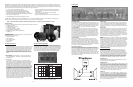
The RS1202 is available as a kit or fully assembled. In kit form, it can be assembled in less than 1 hour. The kit is fun and easy to as-
semble and will provide the bass you’ve been missing in your home theater or sound system.
Note: If you purchased the system pre-assembled please skip to the “Optimum System Equalization” section.
Parts Inventory
Your Reference Series RS1202 Subwoofer System should include the following:
• 1 Subwoofer cabinet
• 2 RSS315HFA-8 12" drivers
• 1 Subwoofer amplifier
• 2 1-lb. bags Acousta-stuf polyfill
• Cap head driver mounting screws
• Amplifier mounting screws (In amplifier box)
• 14 AWG wire
Installation Tools
The Reference Series Subwoofer System can be assembled with
the following tools and materials:
• Phillips screwdriver
• 5/32" hex driver
• Wire cutters/strippers
• Spray adhesive
• Utility knife
(2) (3)
Thank You...for purchasing the Dayton Audio RS1202 Subwoofer System. It will fill almost any home with the deepest, loudest, lowest
distortion sub-bass imaginable. The opposed side-firing design ensures the 12" Reference Series drivers’ prodigious output excites your
senses and not the enclosure’s structure. The RS1202 powered subwoofer is fully equipped with features that represent the kind of qual-
ity and performance that customers have come to expect from Dayton Audio, like:
• Parametric equalizer for optimum response and maximum
integration circuit eliminates harsh overload conditions and
protects drivers
• Low distortion, superior definition, and bone-rattling
output—flat response to 27 Hz
• Gray vinyl matches modern A/V furniture and accessories
Optimum System Equalization
The RS1202 was designed to deliver optimum results through the
use of carefully determined parametric equalization settings. The
intitial configuration, which will provide the specified performance in
most listening rooms, is set thusly—Frequency: 25 Hz, Bandwidth:
0.2, and Level: +6 dB. Variations are of course at the user’s discre-
tion; for more information about the parametric equalizer, please
review the Parametric Equalizer section as detailed on page 3.
Power input:
This unit features an IEC grounding type power input connector.
The IEC connector allows the user to quickly exchange the power
cord if it is damaged, or if a longer cord is desired. The IEC inlet
connector also features an integrated fuse holder that contains the
AC line fuse.
Power LED:
When the power switch is moved to the “on” position, the LED will
illuminate a bright green, to indicate that the amplifier is fully op-
erational and ready to receive typical music program. As the input
signal increases to the onset of clipping the LED will turn from
green to a yellow color and finally to red, which indicates that the
clip limiting circuitry is activated. If an input signal (3 mV or greater)
is not detected for 10 to 15 minutes, the amp will go to “stand by”
mode and the LED will change to a dim green.
Phase:
This two-position (NOR = 0° phase and REV = 180° phase) switch
helps to compensate for differences in the acoustical and electrical
characteristics between the subwoofer and the main system speak-
ers. The relative locations of speakers in the system can cause
significant disturbances in speaker interaction due to time delay
issues, or the destructive phase interferences that can occur at cer-
tain frequencies. The use of this switch in conjunction with altering
the location of the subwoofer can have a dramatic effect on system
integration. The “NOR” setting would be considered the normal or
default setting, but be sure to experiment during system set-up.
Parametric Equalizer
The amplifier features a fully parametric equalizer to help you to
achieve the best possible subwoofer performance. Professional
sound engineers have for many years considered the parametric
EQ to be one of the most accurate, versatile, and high fidelity tools
for audio enhancement. A greater degree of control can be achieved
when using the EQ’s unique ability to vary the frequency to be af-
fected, the amount of boost or cut, and the width or narrowness at
the selected frequency. The equalizer can be configured for either
broad, gentle tone shaping or precise correction, it’s up to you!
EQ-Frequency:
Establishes the specific frequency at which EQ boost or cut may
be applied between 18 Hz and 80 Hz.
EQ-Bandwidth:
Determines how narrow or wide the EQ curve will be within a range
of 0.1 to 1.0. If for example a frequency of 60 Hz were selected
along with a Q of 0.1, the frequencies to either side of 60 Hz would
be less affected. This is a narrow bandwidth that could be useful for
“surgically” removing an offending peak without disturbing adjacent
frequencies. At the other extreme, a Q of 1 would result in a much
broader effect which could be used for smooth overall bass boost or
cut, to balance the overall tone character of the sub.
EQ-Level:
Permits the application of up to 6dB of boost or 14.5dB of cut at
the selected frequency and bandwidth. Setting the control at the
0 position effectively removes the EQ from the circuit path.
It is good to remember that high levels of boost reduce amplifier
headroom; it is the same as turning up the low pass gain control
but only at the selected EQ frequencies. It would be helpful to re-
duce or increase the low pass gain control to balance the amount
of cut or boost applied by the EQ.
• 2.1 cu. ft. true acoustic suspension cabinet
• Opposed side-firing drivers cancel cabinet vibration
• Heavily braced 1" and 2” MDF cabinet wall construction
• Dual high-Xmax Dayton Audio RSS315HFA-8 12" drivers
• Patented, ultra-efficient 950 watt RMS Class AB/Class G amplifier
• Auto on/off with standby mode
• User-adjustable gain and crossover frequency controls
Assembly Instructions
A. Install amplifier
Cut off connectors on amplifier output wires—be careful to leave
enough wire length to connect the speaker. Feed wire through
hole in divider. Insert amplifier into the back of the cabinet. The
amplifier features a thick foam gasket that provides an airtight
seal so no caulk is needed. Be sure to position the amp so
that the controls and printing are oriented correctly. Using the
supplied Phillips head screws, tighten down the amp in a “star”
pattern.
B. Install stuffing
“Fluff” and apply approximately 1.7 lbs of the supplied 2 lbs.,
using spray adhesive – remember to add stuffing behind the
window brace.
C. Install Drivers
Lay cabinet on one side. Be careful not to damage skirting!
Insert driver 1 (it doesn’t matter which side of the cabinet), align
holes and tighten screws. IMPORTANT: Match the mounting
flange holes to the threaded holes in the cabinet. Insert each
mounting screw one at a time and turn each by hand to start
the screw into the threaded hole in the cabinet. You may need to
move the driver from side to side to get each screw started. Do
not tighten the screws until all the mounting screws have
been started by hand. Be careful not to cross thread the
screws! After all mounting screws have been started, tighten
the screws in a “star” pattern using a 5/32” hex driver. Carefully
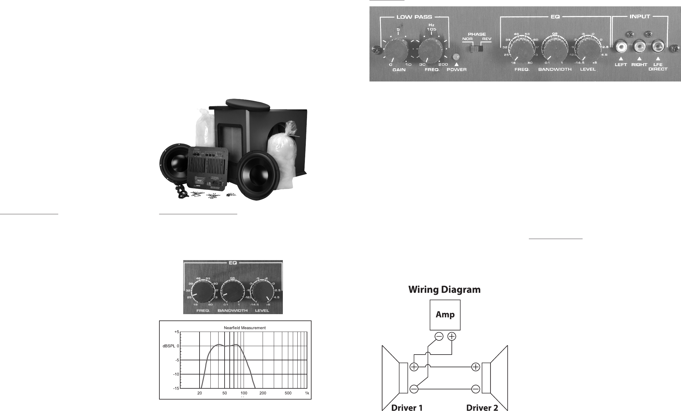
lay cabinet on other side. Using the wiring diagram on page 3 as
a guide, strip amp wires and connect to driver 1 while observing
polarity. Strip supplied speaker wire at both ends and connect
to driver 1 while observing polarity. Connect remaining ends of
speaker wire to driver 2 while observing polarity. Insert driver 2,
align holes and tighten screws. Install the grills. You are finished
with the assembly of the subwoofer system. Be careful, the as-
sembled subwoofer system is very heavy!
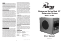
Control Panel
Nearfield measurment with the following settings: Frequency = 25 Hz;
Bandwidth = 0.2; Level = +6dB; Low Pass Filter = 90 Hz.
Left/Right inputs:
RCA style jacks that will accept standard line level inputs from a pre-
amp level source. They will accept a stereo signal and internally com-
bine it into mono. Both left and right input jacks should be connected
to the source in order to drive the amplifier to full output. The use of a
“Y” cord is suggested if a mono source is all that is available.
LFE direct input:
RCA jack that will accept a signal from the mono LFE (Low Fre-
quency Effects) output on a pre-amp or receiver that is equipped
with a dedicated sub bass output. This input bypasses the ampli-
fier’s own internal low pass filter circuitry, relying instead on the
processed output provided by the source equipment. This would
be the recommended connection for most home theatre surround
sound receivers and pre-amps. We would also suggest the use of
the LFE input when an external line level electronic crossover or
frequency dividing network is used.
Low Pass, Gain:
Will match the amplifier’s input sensitivity to the output of the
preamp source. If the source output has a variable control, we
recommend that the user spend a moment or two determining the
best balance between the two controls. When a balance is found
between low noise, linear level control, and sufficient level to drive
the amp to the required output, the gain knob can be considered to
be the “volume control” for the subwoofer system.
Low Pass, Frequency:
This control is used to establish the highest frequency that the
subwoofer will reproduce and has a range between 30 and 200 Hz.
If your main speakers have good bass capability, you could set the
control to a fairly low value at 40, 60, or even 100 Hz. If the main
speakers are smaller or do not have much bass output, set the
control higher. Experiment with the amount of “overlap” that you will
experience when all speakers are playing in the same range. This
can be helpful when integrating the subwoofer with the rest of the
system and with the room.