


(2) (3)
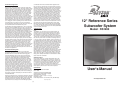
Thank You...for purchasing the RS1200 Subwoofer System.
It produces accurate and powerful bass, making it perfect
for home theater or music listening rooms. The rigidly
braced cabinet features a textured matte black finish and is
coupled to the floor using our “black chrome” spikes set. The
Reference Series driver is precision crafted using only the
finest components and features a build quality that rivals the
best European drivers. This system is available as a kit or fully
assembled. In kit form, it can be assembled in less than 1 hour.
The kit is fun and easy to assemble and will provide the bass
you’ve been missing in your home theater or sound system.
Note: If you purchased the system pre-assembled
please skip to the “Features” section.
Parts Inventory
Your Reference Series RS1200 Subwoofer System should
include the following:
•
1 Subwoofer cabinet
•
1 Reference Series driver
•
1 Subwoofer amplifier
•
1 Speaker cabinet spike set
•
Convoluted acoustic foam
•
Cap head driver mounting screws
•
Amplifier mounting screws (In amplifier box)
• Speaker sealing caulk
Installation Tools
The Reference Series Subwoofer System can be assembled
with the following tools:
•
Phillips Screwdriver
•
5/32” Hex Driver
•
Wire cutters/strippers
•
Utility knife
Assembly Instructions
A. Install spiked feet
We recommend that you install the feet first so you can
quickly identify the cabinet bottom for proper orientation
while installing the amp and driver. To ease assembly, all
t-nuts have been installed in the cabinet at the factory.
The t-nuts included with the spike feet set are extra and
can be discarded after assembly. The pointed tip of the
spiked foot unscrews, make sure it is in place and hand
tight. Install the threaded rod as far as it will go into
the other end of the spiked foot. Next, screw the foot
into one of the four holes on the bottom of the cabinet
until it is flush and hand tight. Repeat procedure for the
other three feet. To ensure an airtight fit, we recommend
putting a small amount of RTV sealant on the threads
and base of the feet before installing to the cabinet.
B. Install amplifier
The amplifier features a thick foam gasket that provides
an airtight seal so no caulk is needed. Insert amplifier
into the back of the cabinet. Be sure to position the amp
so that the controls and printing are oriented correctly.
Using the supplied Phillips head screws, tighten down
the amp in a “star” pattern.
C. Install foam
Put the foam in the cabinet through the front and form it
around the inside of the cabinet. You will have to cut the
foam with a utility knife to fit it around the brace. Be sure
the flat side of the foam is against the cabinet walls. It’s a
good idea to use some spray adhesive to tack the foam
to the walls.
D. Install Driver
To ease assembly, all t-nuts have been installed in the
cabinet at the factory. The t-nuts included with the cap
head driver mounting screws are extra and can be
discarded after assembly. First, place the cabinet on its’
back taking care not to damage the amplifier controls.
Pull the speaker wire from the back of the amplifier
out through the driver hole. Cut off the connectors
and strip back the insulation on the wire. Be careful to
leave enough length in the wire to connect the speaker.
Connect the wire to the speaker, while observing the
proper polarity (red to positive speaker terminal, black
to negative speaker terminal). Place speaker sealing
caulk over the gasket on the back of the speaker. Place
driver in the opening and match the mounting flange
holes to the threaded holes in the cabinet. Insert each
mounting screw one at a time and turn each by hand
to start the screw into the threaded hole in the cabinet.
You may need to move the driver from side to side to get
each screw started. Do not tighten the screws until
all the mounting screws have been started by hand.
Be careful not to cross thread the screws!
After all
mounting screws have been started, tighten the screws
in a “star” pattern using a 5/32” hex driver. Install the
grill. You are finished with the assembly of the subwoofer
system.
Features
The RS1200 powered subwoofer is fully equipped with features
that represent the kind of quality and performance that customers
have come to expect from the Dayton Loudspeaker line, like:
• High Xmax Reference Series driver
• Patented Class G tracking amplifier for more power and
greater efficiency
• Low distortion electronic and speaker components
• Parametric equalizer for optimum response and
maximum integration
• Soft clip” circuit eliminates harsh overload conditions and
protects drivers
• Auto on/off with standby mode
• Convenient connections and controls for easy hook-up and
system integration
• User-adjustable crossover frequency control
• Gain control for easy volume adjustment
• Industry-leading customer service and technical support
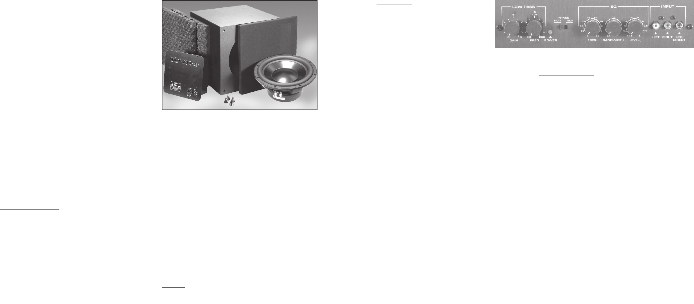
Control Panel
Left/Right inputs:
RCA style jacks that will accept standard
line level inputs from a pre-amp level source.
They will accept a stereo signal and internally
combine it into mono. Both left and right input
jacks should be connected to the source
in order to drive the amplifier to full output.
The use of a “Y” cord is suggested if a mono
source is all that is available.
LFE direct input:
RCA jack that will accept a signal from the mono LFE (Low
Frequency Effects) output on a pre-amp or receiver that
is equipped with a dedicated sub bass output. This input
bypasses the amplifier’s own internal low pass filter circuitry,
relying instead on the processed output provided by the source
equipment. This would be the recommended connection for
most home theatre surround sound receivers and pre-amps. We
would also suggest the use of the LFE input when an external
line level electronic crossover or frequency dividing network is
used.
Power input:
This unit features an IEC grounding type power input connector.
The IEC connector allows the user to quickly exchange the power
cord if it is damaged, or if a longer cord is desired. The IEC inlet
connector also features an integrated fuse holder that contains the
AC line fuse.
Low Pass, Gain:
Will match the amplifier’s input sensitivity to the output of the
preamp source. If the source output has a variable control, we
recommend that the user spend a moment or two determining
the best balance between the two controls. When a balance is
found between low noise, linear level control, and sufficient level
to drive the amp to the required output, the gain knob can be
considered to be the “volume control” for the subwoofer system.
Low Pass, Frequency:
This control is used to establish the highest frequency that the
subwoofer will reproduce and has a range between 30 and 200
Hz. If your main speakers have good bass capability, you could
set the control to a fairly low value at 40, 60, or even 100 Hz. If
the main speakers are smaller or do not have much bass output,
set the control higher. Experiment with the amount of “overlap”
that you will experience when all speakers are playing in the
same range. This can be helpful when integrating the subwoofer
with the rest of the system and with the room.
Power LED:
When the power switch is moved to the “on” position, the LED
will illuminate a bright green, to indicate that the amplifier is fully
operational and ready to receive typical music program. As the
input signal increases to the onset of clipping the LED will turn
from green to a yellow color and finally to red, which indicates
that the clip limiting circuitry is activated. If an input signal (3 mV
or greater) is not detected for 10 to 15 minutes, the amp will go
to “stand by” mode and the LED will change to a dim green.
Phase:
This two-position (NOR = 0
° phase and REV = 180° phase)
switch helps to compensate for differences in the acoustical
and electrical characteristics between the subwoofer and the
main system speakers. The relative locations of speakers in
the system can cause significant disturbances in speaker
interaction due to time delay issues, or the destructive phase
interferences that can occur at certain frequencies. The use
of this switch in conjunction with altering the location of the
subwoofer can have a dramatic effect on system integration.
The “NOR” setting would be considered the normal or default
setting, but be sure to experiment during system set-up.
Parametric Equalizer
The amplifier features a fully parametric equalizer to help
you to achieve the best possible subwoofer performance.
Professional sound engineers have for many years considered
the parametric EQ to be one of the most accurate, versatile,
and high fidelity tools for audio enhancement. A greater degree
of control can be achieved when using the EQ’s unique ability
to vary the frequency to be affected, the amount of boost or
cut, and the width or narrowness at the selected frequency.
The equalizer can be configured for either broad, gentle tone
shaping or precise correction, it’s up to you!
EQ-Frequency:
Establishes the specific frequency at which EQ boost or cut
may be applied between 18 Hz and 80 Hz.
EQ-Bandwidth:
Determines how narrow or wide the EQ curve will be within a
range of 0.1 to 1.0. If for example a frequency of 60 Hz were
selected along with a Q of 0.1, the frequencies to either side
of 60 Hz would be less affected. This is a narrow bandwidth
that could be useful for “surgically” removing an offending peak
without disturbing adjacent frequencies. At the other extreme,
a Q of 1 would result in a much broader effect which could
be used for smooth overall bass boost or cut, to balance the
overall tone character of the sub.
EQ-Level:
Permits the application of up to 6dB of boost or 14.5dB of cut at
the selected frequency and bandwidth. Setting the control at
the 0 position effectively removes the EQ from the circuit
path. It is good to remember that high levels of boost reduce
amplifier headroom; it is the same as turning up the low pass
gain control but only at the selected EQ frequencies. It would
be helpful to reduce or increase the low pass gain control to
balance the amount of cut or boost applied by the EQ.
Installation
The reasonable size and neutral appearance of the RS1200
will provide the user with tremendous flexibility when the
time comes to choose a location for the most satisfactory
performance. Please be aware that the powerful woofer motor
assembly can emit stray magnetic fields, and these fields can
have a detrimental effect on TV and computer screens, and
magnetic storage media such as videotapes, audio cassettes,
and computer data storage discs like floppies and zips. Try to
maintain a safe distance of 2 to 3 feet from any of these items
to prevent damage, or the loss of recorded data. The side of
the subwoofer that includes the control panel should be kept
at least 2 to 4 inches from a wall or other surface, but special
care should be taken to avoid close proximity to upholstered
surfaces or drapes. Please make sure that the control panel
has enough free air space around it so that proper cooling
can take place. Refrain from using the system in wet or rainy
outdoor locations.