


XLS Series Power Amplifi ers
Operation Manual
page 10
4 Operation
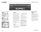
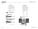
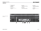
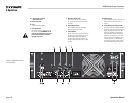
4.3 Back Panel Controls
and Connectors
G. Power Connector
H. Fuse
Provides overload protection.
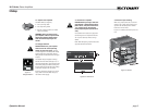
I. Voltage Selector
Two-position switch is factory-set to coun-
try-specifi c voltage. WARNING: Do not
operate your amplifi er with an incor-
rect voltage selected or amplifi er
damage may result.
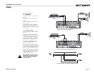
J. Male XLR Signal Links
One per channel; male XLR connectors
are provided for daisy-chaining to other
amplifi ers.
K. Balanced XLR Inputs
One per channel; three-pin female XLR
input connectors are provided.
L. Filter Switches
One per channel; three-position switch sets
the internal high-pass fi lter frequency. Fre-
quency setting is 30 Hz when switch is
in left position; 15 Hz when switch is cen-
tered; and bypassed when switch is in right
position.
M. Limiter Switch
Offers loudspeaker protection against mod-
erate amplifi er clip when set to the “IN”
position.
N. 5-Way Binding Post Output Jacks
One pair per channel; accept banana plugs,
spade lugs or bare wire. Note: Binding post
outputs on European models come with
safety plugs installed to prevent banana
plugs from being inserted. Note that it is
possible to lever the caps out of the bind-
ing posts, but this will invalidate the prod-
uct safety approvals in some territories.
The side entry positions for these connec-
tors should therefore be used if possible.
Figure 4.2 Back Panel Controls
and Connectors