


2–6
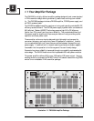
FM1000A User’s Manual
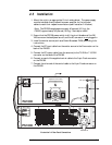
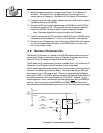
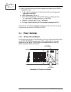
2.6 Remote I/O Connection
LOCAL
MAXIMUM
+5V
LOCAL
POWER
ADJUST
MINIMUM
REMOTE
TANSMITTER
CONTROL
SW3
RAISE
SW4
LOWER
SW5
R62
Electro-
Control
Circuit
REMOTE
RAISE POWER
Pin 4
Remote I/O Conn.
REMOTE
LOWER POWER
Pin 15
Remote I/O Conn.
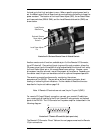
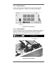
Illustration 2–5 Local and Remote Functions
The Remote I/O Connector on the back of the PA1000 allows remote control and
monitoring of Certain transmitter functions. There are three basic control func-
tions—AC on/off, RF power level adjustment, and RF down/off.
The AC power on/off remote control function, available at pin 7 of the Remote I/O
Connector, turns DC power to the PA on when the pin is grounded.
The RF power level adjustment remote control function has an internal maximum
limit set on the Metering and Control Board. The Local Power Adjust (R62) sets
the maximum limit of RF power output. The limit is set by placing the Remote/
Local switch (SW5) in the LOCAL position and adjusting the Local Power Adjust to
your desired maximum limit (see illustrations 2–5 and 2–6). However, for any
remote operation to work, the Remote/Local slide switch
must be in the REMOTE
position. Then the on-board remote RAISE and LOWER push buttons and any
external remote switches attached to pins 4 and 15 of the I/O Connector can adjust
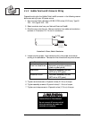
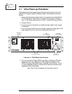
8. Using the supplied connector, tie together pins 6 and 7 of the Remote I/O
connector. The amplifier will not operate without this connection or a
remote switch on these pins. (See Section 2.6 for Remote I/O connection.)
9. If monitoring of the output signal is desired, connect the RF monitor cable to
the BNC connector on the PA1000.
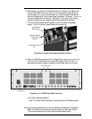
10. Connect the DC input/output cables between the PA1000 and the PS1000 as
illustrated (Illustration 2–4). The connector end with the ground lead con-
nects to the PA1000. Be sure to attach the ground leads as indicated.
Note: The power lead shield is only grounded at the PA chassis.
11. Install the covers over the DC terminals of the PA1000 and the PS1000 using
hardware form the hardware kit (1/4–inch X 6–32 bolts with lock washers).
12. Connect to your AC power source by inserting the Hubble Twist-Lock connec-
tor into the female Hubble connector on the PS1000 and turn to the right
until the connection locks.