


Micro-Tech 2400 Amplifier Service Manual
15
Electrical Checkout Procedures
Procedure Short: Inject a 60 Hz sine wave at 5 VAC
minimum output. After establishing signal, short the
output for 10 seconds.
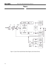
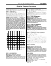
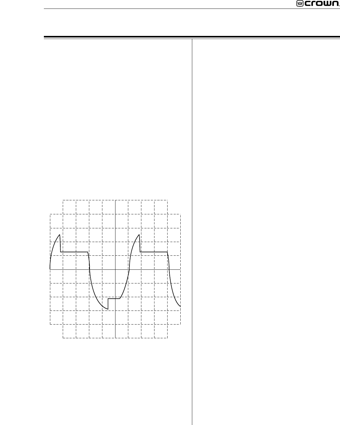
TEST 14: ODEP LIMITING
Spec: No oscillation on ODEP Limiting wave form;
either channel controls limiting in Parallel Mono Mode.
Initial Conditions: Controls per standard; rag or other
obstruction blocking fan so that it does not turn.
Procedure: Load the amplifier to 4 ohms on each
channel. Inject a 60 Hz sine wave and adjust for 35
Vrms at the output. After a few minutes observe a wave
form similar to Figure 5. Remove the input signal from
both channels and allow the amplifier to cool for a few
minutes. Switch the amplifier to Parallel Mono and
remove the load from Channel 1. Inject the signal into
Channel 1 and observe that ODEP limiting occurs at
the output of both channels. Remove the load from
Channel 2, and install the load on Channel 1. Again,
observe that both channels limit. Return all amplifier
controls to standard initial conditions. Remove the fan
obstruction.
TEST 15: LF PROTECTION
Spec: Amplifier mutes for low frequency.
Initial Conditions: Controls per standard.
Procedure: No load. Inject a 0.5 Hz 6 volt peak-to-peak
square wave, or a 2 Hz 6VAC sine wave into each
channel and verify that each channel cycles into mute.
TEST 16: SIGNAL TO NOISE RATIO
Spec: 100 dB below rated 8 ohm power 20 Hz to 20
kHz. 105 dB A-Weighted.
Initial Conditions: Controls per standard. Short inputs.
Procedure: Load each channel to 8 ohms. Measure
less than 645 µV at the output of each channel (20 Hz-
20 kHz bandpass filter).
TEST 17: TURN ON TRANSIENTS
Spec: No dangerous transients.
Initial Conditions: Controls per standard.
Procedure: From an off condition, turn on the amplifier
and monitor the output noise at the time of turn on.
Note: Turn on noise may increase significantly if the
amplifier is cycled off and on.
TEST 18: TURN OFF TRANSIENTS
Spec: No dangerous transients.
Initial Conditions: Controls per standard.
Procedure: From an on condition, turn off the amplifier
and monitor the output noise at the time of turn off.
Note: Turn off noise may increase significantly if the
amplifier is cycled off and on.
TEST 19: INTERMODULATION DISTORTION
Spec at 0 dB Output: 0.01%.
Spec at –35 dB Output: 0.05%.
Initial Conditions: Controls per standard.
Procedure: Load each channel to 8 ohms. Inject a
SMPTE standard IM signal (60 Hz and 7 kHz sine
wave mixed at 4:1 ratio). Set the 60 Hz portion of the
sine wave to 51.5 Volt RMS. Set the 7 kHz portion to
25%. With an IM analyzer measure less than 0.01%
IMD. Repeat test at –35 dB (reference 51.5 Volt RMS,
60 Hz portion) and measure less than 0.05% IMD.
TEST 20: CLIPPING
Spec: No protective action during test.
Initial Conditions: Controls per standard.
Procedure: Load each channel to 8 ohms. Inject a 1
kHz sine wave at each input and drive output 6 dB into
clip for 10 seconds. The amplifier should not activate
any protective circuits (ODEP, Fault, or LF Protection).
POST TESTING
After completion of testing, if all tests are satisfactory,
the amplifier controls should be returned to the posi-
tions required by customer. If conditions are unknown
or unspecified, factory settings are as follows:
Level Controls: 9 to 11 O’Clock.
Sensitivity Switch: 0.775V U.S., 1.4V International.
Stereo/Mono Switch: Stereo.
Ground Lift: Lift.
Power: Off.
Figure 5. ODEP Limiting Wave Form