


Operation Manual
Macro-Tech MA-24X6 & 36X12 Power Amplifiers
page 16
4.3 Options
4.3.1 PIP Modules
Versatile PIP (Programmable Input Processor)
modules provide flexible expansion features
that can be added to customize the amplifier.
PIP modules plug into the connector inside the
back panel of the amplifier.
PIP modules are available with a features rang-
ing from error-driven compressor/limiters to IQ
control. Visit the Crown website at
www.crownaudio.com, or contact Crown Tech-
nical Support, for descriptions of available PIP
modules.
4.3.2 IQ-PIP-USP2 Adapter
The IQ-PIP-USP2 Adapter allows the amplifier
to accept the Crown IQ-PIP-USP2 module,
which offers remote control and monitoring via
Crown’s Smart Amp™ IQ features set, plus a
wide range of digital signal processing capabil-
ities
Features:
• 24-bit, 48-kHz sampling rate for analog to
digital conversion.
• Programmable DSP filters.
• Greater than one-half second of signal
delay for each channel.
• Input Signal Compressor/Limiter, Ther-
mal Limiter and Clip Eliminator for each
channel.
• Presets for easy recall of settings.
• Auto-Standby for reduced energy costs.
• Error reporting.
• Logic input and output.
• Listen Bus allow easy connection to an
audio monitoring system.
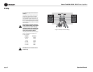
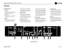
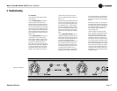
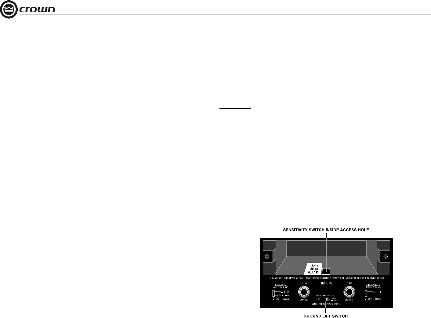
4.3.3 Input Sensitivity Switch
The Input Sensitivity Switch is located inside
the PIP compartment at the back of the ampli-
fier (Figure 4.1). It is set at the factory to 0.775
volt for rated output into 8 ohms. It can also be
switched to a sensitivity of 1.4 volts, or a fixed
voltage gain of 26 dB (4.8 volts for rated out-
put). At 26 dB voltage gain, the equivalent input
sensitivity is:
Macro-Tech 24X6:
3.1V for Channel 1, and
2.2V for Channel 2.
Macro-Tech 36X12:
4.8V for Channel 1, and
2.6V for Channel 2.
How to change the input sensitivity:
1. Turn off the amplifier and disconnect its
power cord from the AC mains power recep-
tacle.
2. Remove the PIP module (two screws).
3. Locate the sensitivity switch access hole
inside the chassis opening as shown in Fig-
ure 4.1. It is located just above the phone
jack inputs.
4. Set the switch to the desired position noted
on the access hole label. The position toward
the front panel sets the sensitivity to 1.4
volts for rated output, the middle position
provides a voltage gain of 26 dB, and the
position toward the back panel sets the sen-
sitivity to 0.775 volt for rated output.
5. Replace the PIP module and restore the
power.
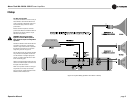
4.3.4 Input Ground Lift Switch
The Input Ground Lift switch is located on the
rear panel (Figure 4.1) and can provide isola-
tion between the input signal ground and the
AC ground. It affects only the phone jack inputs
and has no effect on the input connectors on
the PIP module. Sliding the switch to the left
isolates or “lifts” the grounds by placing an
impedance between the sleeve of each phone
jack and the circuit ground.
When a PIP module is plugged into the ampli-
fier, only the noninverted and inverted signal
lines are connected in parallel with the corre-
sponding lines of the input phone jacks. The
signal grounds are not paralleled. For example,
XLR pins 2 and 3 are connected in parallel with
the tip and ring of the corresponding phone
jack. However pin 1 of the XLR is not con-
nected in parallel with the sleeve of the phone
jack.
4 Advanced Features
and Options
Figure 4.1 Input Sensitivity and Ground Lift Switches