


Operation Manual
I-Tech Series Power Amplifiers
page 10
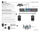
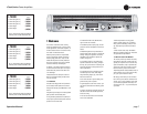
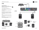
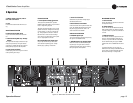
2.3.2 Choose Input Wire and Connectors
Crown recommends using pre-built or professionally wired, bal-
anced line (two-conductor plus shield), 22-24 gauge cables and
connectors. Use 3-pin male XLR connectors.
Unbalanced line may also be used but may result in noise over
long cable runs.
Figure 2.1 shows connector pin assignments for balanced analog
wiring or AES/EBU digital wiring. Figure 2.2 shows connector pin
assignments for unbalanced analog wiring.
I-Tech models with a CN suffix accept CobraNet network signals.
With CobraNet, you can send digital audio and amplifier
IQ
®
-control signals on the same Category 5 cable. This single
cable plugs in to the Network connector on the rear panel.
NOTE: Custom wiring should only be performed by qualified per-
sonnel.
Figure 2.1
Balanced Analog Input Connector Wiring or
AES/EBU Digital Connector Wiring
Figure 2.2 Unbalanced Analog Input Connector Wiring
2 Setup
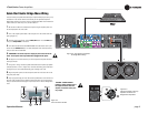
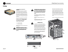
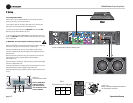
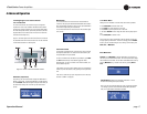
2.3.3 Choose Output Wire and Connectors
Crown recommends using pre-built or professionally wired, high-
quality, two- or four-conductor, heavy gauge speaker wire and
connectors. Use Class 1 output wiring. You may use a 4-pole
Speakon connector (Figure 2.3) or banana plugs, spade lugs, or
bare wire for your output connectors (Figure 2.4). To prevent the
possibility of short-circuits, wrap or otherwise insulate exposed
loudspeaker cable connectors.
CAUTION – SHOCK HAZARD: Potentially lethal voltages
exist at the output connectors when the amplifier is
turned on and is passing a signal.
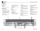
Using the guidelines below, select the appropriate size of wire
based on the distance from amplifier to speaker.
Distance Wire Size
up to 25 ft. 16 AWG
26-40 ft. 14 AWG
41-60 ft. 12 AWG
61-100 ft. 10 AWG
101-150 ft. 8 AWG
151-250 ft. 6 AWG
CAUTION: Never use shielded cable for output wiring.
Figure 2.4
5-Way Binding Post Connections
Figure 2.3
Left: Speakon
Output Connector on Back Panel
Right: Speakon
Cable Connector