


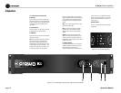

K Series Power Amplifiers
page 11
Operation Manual
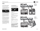
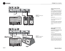
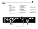
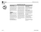
4.3 Back Panel Controls and
Connectors
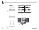
Figure 4.3 below points out the controls and
connectors on the back panel of the K Series
amplifiers. The K1 and K2 look identical except
for product nameplates and fuse specifications.
E. Bridge Output Switch
This switch selects whether or not the output
signal is bridged across the two channels. To
operate the amplifier in bridge-mono mode, set
this switch to ON. To operate the amplifier in
dual mode, set this switch to OFF. See Section
3.6.1 for more detail.
F. “Y” Input Switch
If you want to feed a mono audio signal to two
channels, each with its own level control, set
the “Y” Input switch to ON. This connects the
input signals of both channels together, in par-
allel. To operate in dual mode, set this switch to
OFF. See Section 3.6.1 for more detail.
G. XLR-type Input Connector
This is a female XLR-type connector, one per
channel, that accepts a balanced or unbalanced
input signal. See Section 3.4 for pin assign-
ments.
H. Input Sensitivity Switch
This switch selects between1.4V sensitivity or
26 dB gain. See Section 3.6.2 for more detail.
I. Phone Jack Input Connector
This is a 1/4-inch phone jack connector, one
per channel, that accepts a balanced or unbal-
anced input signal. See Section 3.4 for terminal
assignments.
J. Power Fuse
This fuse protects the high-voltage power
supply.
K. Power Cord
This permanently attached cable conducts the
AC mains electricity to the amplifer.
L. Output Connectors
These 5-way binding-post connectors (one pair
per channel) provide the amplifier output signal
for connection to loudspeakers. The load can
be connected in stereo (one load per channel)
or in bridge mono (one load across the positive
terminals of both channels). When using
bridge-mono mode, be sure to set the Bridge
Output switch to ON. See Sections 3.6.3 and
3.6.4 for details.
Figure 4.3 Back Panel Controls and Connectors
4 Operation