Operation Manual
CE Series Power Amplifiers
page 14
3 Operation
3.4 Back Panel Controls and
Connectors
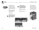
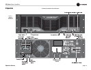
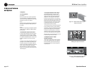
Input Sensitivity Switch
This two-position Input Sensitivity switch is located
near the input connectors. It lets you select between
1.4 V input sensitivity or 26 dB gain. Please see
Section 2.7 in this manual for details.
Mode Switch
This two-position switch selects either Stereo or
Bridge-Mono mode of operation. Stereo mode pro-
vides identical power output to each of the two
amplifier output channels. Bridge-Mono mode
combines the two amplifier output channels into a
single mono channel with twice the voltage of a sin-
gle stereo channel.
Do NOT select Bridge-Mono mode without
first making sure the amplifier has been
wired in a Bridge-Mono configuration. For
more information on wiring for Bridge-Mono mode,
see Section 2.6.2.
Fault Jack
This is an RJ-11 jack (which looks like a telephone
jack). By attaching a signaling device to the Fault
jack, you can monitor the amplifier’s Fault status
from a remote location. See Section 4.2.2 for more
information on fault monitoring.
Barrier Block Inputs
For each channel, this row of screw terminals pro-
vides a balanced input, which is in parallel with the
channel’s Combo input connector.
Neutrik Combo Input
One per channel, this combination 1/4-inch phone
jack and XLR connector provides a balanced or
unbalanced input.
Neutrik Speakon
®
Output
One per channel, this Neutrik Speakon
®
connector
with four terminals connects to loudspeakers.
See Section 4.2.2 in this manual for more informa-
tion on fault monitoring and suggestions for signal-
ling device circuity.
Some fault conditions may cause the output of the
amplifier to be muted.
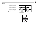
Clip Indicators
These are two red LEDs (one per channel). The Clip
Indicator turns on when distortion is audible in the
amplifier output.
Signal Indicators
These are two green LEDs (one per channel). The
Signal Indicator illuminates when a signal (> –40
dBm) is present at the INPUT of the amplifier for
that channel. Because these indicators receive the
signal before the level controls, they can be used to
troubleshoot wiring problems within a system. If the
Signal indicator for a channel is not lit, no signal is
reaching the amplifier on that channel.
Power Indicator
The green Power indicator lights when your CE-
Series amp has been turned on and has power.
Level Controls
Two rotary detented Level controls (one for each
channel) are are used to adjust each channel’s out-
put.
If you wish, the level control knobs may be pulled
from the front panel and the holes plugged with the
supplied caps to minimize tampering of control set-
tings.
3.3 Front Panel Controls and
Indicators
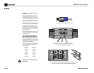
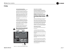
Power Switch
The power switch turns the amplifier on (“I”) or off
(“O”).
Note that dangerous voltages may still be
present in the amplifier even when the
power switch is in the off (“O”) position.
Before moving the amplifier or making any wiring or
installation changes, it is important to also discon-
nect the power cord from the amplifier or power
source.
Reset Switch
The push-button reset switch is used to reset the
circuit breaker that protects the power supply.
Fault Indicators
Two red LEDs (one for each channel) are located on
the front panel. The Fault Indicators are normally
OFF, but will blink under five different conditions:
1. When the amplifier is first powered up, until the
unit is ready for operation.
2. If the heatsinks reach a temperature above normal
working limits.
3. If the transformer thermal protection circuit is
activated.
4. If the amplifier output wires develop a short-cir-
cuit.
5. If the amplifier output stage stops operating.
The fault status of the amplifier can also be moni-
tored remotely by attaching a signalling device to
the Fault jack located on the amplifier back panel.


