


Operation Manual
CE2000TX Power Amplifier
page 10
3 Setup
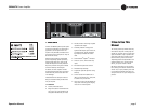
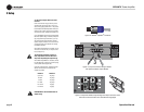
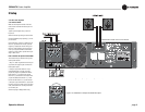
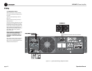
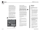
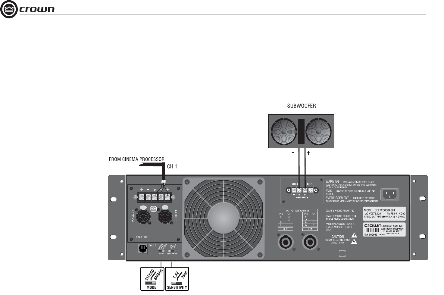
Figure 3.11 Typical System Wiring, Bridge Mono Mode
3.6.2 Bridge-Mono Mode
Make sure the amplifier is turned off and the
level controls are turned down before you wire
the system.
Typical input and output wiring is shown in
Figure 3.11.
INPUTS: Connect input wiring to lower-num-
bered channel pair.
OUTPUTS: Connect the speaker across the posi-
tive terminals of each channel pair. Do not use
the negative terminals of the channel pair when
the pair is being operated in Bridge-Mono mode.
Refer to Section 3.5 for output connector pin
assignments. Make sure the Mode switch is set
to the “Bridge” position when operating in
Bridge-Mono mode.
NOTE: Turn down (full CCW) the Channel
2 level control when operating the
channel pair in Bridge-Mono mode, as
the Channel 1 level control works both
channels.
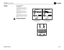
NOTE: Crown provides a reference of wiring pin
assignments for commonly used connector
types in the Crown Amplifier Application Guide
available at www.crownaudio.com.
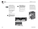
SHOWN WITH OPTIONAL CEAS1 OUTPUT MODULE