


Commercial Audio Series Mixer-Amplifiers
page 11
Operation Manual
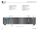
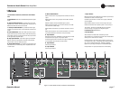
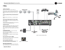
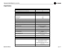
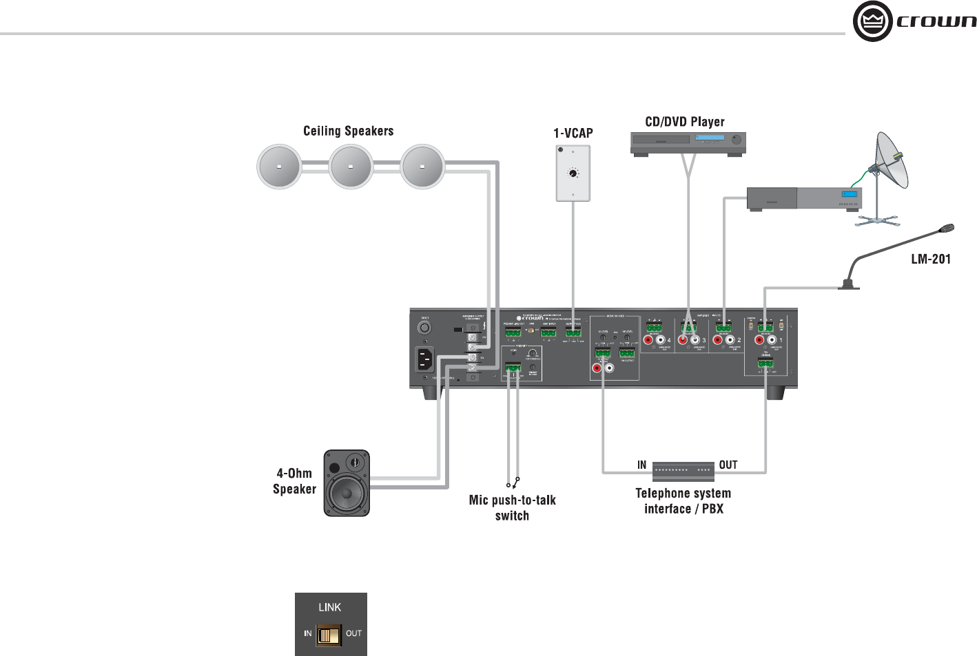
2.5 Wire Your System
Typical input and output wiring is shown in Figure 2.10.
INPUTS: For Input 1, connect a microphone or balanced line-level
signal to the Input 1 balanced input. Set the Mic/Line switch accord-
ingly. Connect unbalanced line-level signals to the RCA input con-
nectors.
For Inputs 2-4, connect a balanced line-level signal to the balanced
input. Connect unbalanced line-level signals to the RCA input con-
nectors.
OUTPUTS: Maintain proper polarity (+/–) on amplifier output con-
nectors.
Connect the Amplifier Output screw terminals to the loudspeaker
loads. Use terminals marked COM and 70V or 100V for constant-
voltage loudspeaker loads. Use terminals marked COM and 4 ohms
for 4-ohm speakers.
Connect the COM terminal to speaker negative (–) lead; connect one
of the other terminals to speaker positive (+) lead.
2.6 Phantom Power
Condenser mics require phantom power to operate. If you are using a
condenser microphone on Input 1, turn on the Phantom Power
Switch on the back of the 140MPA. The microphone must be able to
work on 15V phantom power, which the 140MPA mic input connector
provides.
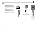
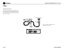
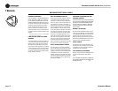
2.7 Link In/Out Switch
This switch (Figure 2.11) affects which signals are heard when
another mixer is wired to the 140MPA.
IN: Any signal applied to the AMP INPUT connector will be mixed
with the input signal(s).
OUT: Only the signal from the AMP INPUT connector will appear at
the amplifier output.
How to link another mixer to the 140MPA:
Connect the extra mixer’s LINE OUT connector to the 140MPA AMP
INPUT connector. Set the Link switch to IN.
How to set up Music-On-Hold output:
Connect 140MPA LINE OUT to the Music-On-Hold input on a tele-
phone system interface/PBX. Set the LINK SWITCH to IN.
How to set up a processing loop:
Connect 140MPA LINE OUT to processor input. Connect processor
output to 140MPA AMP INPUT connector. Set the Link switch to OUT.
2 Setup
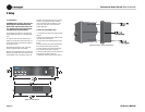
Satellite Receiver
Figure 2.10 Input and Output Wiring
Figure 2.11 Link In/Out Switch