


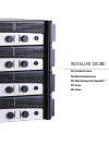

INSTALLED SOUND
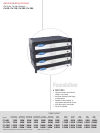
SPECIFICATIONS
Frequency Response (at 1 watt, 20 Hz - 20 kHz):
±0.5 dB.
Phase Response (at 1 watt, 10 Hz - 20 kHz): ±35°.
Signal to Noise Ratio below rated power (20 Hz to
20 kHz): 100 dB unweighted.
Total Harmonic Distortion (THD) at 1 watt, from
20 Hz to 20 kHz: < 0.05%.
Intermodulation Distortion (IMD) 60 Hz and 7
kHz at 4:1, from 163 milliwatts to full bandwidth
power: < 0.05% (typical).
Damping Factor: 10 Hz to 400 Hz: >180.
Crosstalk (below rated power, 20 Hz to 1 kHz): >
80 dB.
Common Mode Rejection (CMR) (20 Hz to 1 kHz):
> 50 dB.
DC Output Offset (shorted input): < ±5 mV.
Input Impedance (nominal): 20 kilohms balanced,
10 kilohms unbalanced.
Maximum Input Level (before input compression):
+ 20 dBu.
Load Impedance: (Note: Safe with all types of
loads)
Stereo: 4/8 and 25 ohms (70V)
Bridge Mono: 8/16 and 50 ohms (100V)
Voltage Gain (at maximum level setting), 1.4V
sensitivity,
4/8 Ohm Operation: 20:1 (26 dB);
70V Operation: 50:1 (34 dB)
100V Operation: 71.4:1 (37 dB)
AC Line Voltage and Frequency Configurations
Available (±10%): 120V/60 Hz, 220/230/240V/50
Hz.
Power Draw at Idle (120VAC mains, all channels
in 4/8 ohm mode): 58W.
Power Draw at Idle (120VAC mains, all channels
in 70V mode): 77W.
Cooling: Continuously variable speed forced air,
front-to-back airflow.
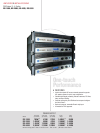
Dimensions (Width, Height, Depth):
CTs 4200: 19 in. (48.3 cm) W x 3.5 in. (8.9 cm)
H x 16.25 in. (41.3 cm) D.
CTs 8200: 19 in. (48.3 cm) W x 5.25 in. (13.3
cm) H x 16.25 in. (41.3 cm) D.
Weight (Net, Shipping):
CTs 4200: 27 lb 8 oz (12.5 kg),
32 lb (14.5 kg)
CTs 8200: 36 lb 6 oz (16.5 kg),
47 lb (21.3 kg).
Front Panel Controls and Indicators
Bridge Mode Indicator: Yellow LED, one per
channel pair, illuminates when the channel pair’s
Mode Switch is set to the “Bridge” position. If Mode
switch is changed while amplifier is powered up,
Bridge LED will flash, indicating that the amplifier
must be powered off and on to reset the Mode.
Ready Indicator: Green LED, one per channel,
illuminates when the channel is initialized and ready
to produce audio output.
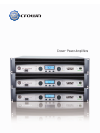
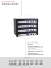
C
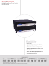
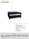
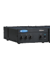
rown’s CTs Multi-Channel Series offers wide flexibility for a wide range of installed sound applica-
tions. CTs Multi-Channel Series amplifiers offer independent selection of high- and low-impedance
operation for each channel pair, making these amps ideal for multi-zone installations.
Signal Indicator: Green LED, one per channel,
illuminates to indicate the presence of analog input
signals above –40 dBu.
Clip Indicator: Red LED, one per channel, illumi-
nates when the THD of the channel’s output signal
rises to a level typically considered as the onset of
audible clipping. The Clip Indicator also will illumi-
nate during Thermal Level Control (TLC) or input
overload.
Thermal Indicator: Red LED, one per channel,
flashes when a state of thermal stress or overload
has caused the channel to shut down. If the power
supply goes into thermal overload, all channel LEDs
will flash.
Fault Indicator: Red LED, one per channel, flashes
when a fault condition has occurred in the channel.
Ventilation Grille: Front-to-rear forced airflow.
Data Indicator: Yellow LED indicates IQ Loop data
activity (if the amplifier is equipped with an IQ-MC
module, and connected to an IQ Loop).
Power Indicator: Blue LED indicates amplifier has
been turned on and AC power is available. Indica-
tor also flashes if the amplifier shuts off due to an
under-/over-voltage condition on the AC mains.
Power Switch: Amplifier is on when the switch is in
the IN position.
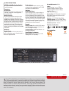
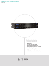
Back Panel Controls and Connectors
AC Power Cord Connector: IEC inlet, type 320;
100/120VAC units: 15A;
220/230/240VAC units: 10A.
Voltage is indicated above IEC inlet.
Output Connectors: One four-pole terminal strip
for every two channels with touch-proof cover.
Accepts up to 10 AWG terminal forks.
Accessory Panel: CTs 4200 accepts an optional
VCA-MC4A module. CTs 8200 accepts an optional
VCA-MC8 module.
Channel Level Controls: One 21-position detented
rotary potentiometer per channel, ranging from
infinity (–70 dB) to 0 dB attenuation.
Input Connectors: Removable Phoenix-style barrier
connectors for balanced input. Also can be used as
a CobraNet input or a backup for CobraNet.
Mode Switch: Used on each consecutive pair of
channels, this four-position switch is used to select
the amplifier’s mode of operation: Dual 8/4 ohms,
Dual 70V, Bridge-Mono 16/8 ohms, and Bridge-
Mono 100V.
Cooling Vents: Front-to-rear forced airflow.
Options
Control Modules: VCA-MC4A: VCA module for CTs
4200A. VCA-MC8: VCA module for CTs 8200.
Wall-mount level control panels for use with VCA
module: 1-VCAP: Single-gang panel with 1 VCA
channel volume control. 4-VCAP: Two-gang panel
with 4 VCA channel volume controls.
T-170V: This is an autoformer that allows 100V
output from the amplifier, and allows other ampli-
fiers without direct constant voltage output to be
easily integrated into distributed systems.
TP-170V: This is a rack-mountable panel with four
autoformers as described above.
Protection Systems
Thermal Level Control (TLC): If an amplifier chan-
nel starts to overheat, the TLC circuit will engage
that channel’s input compressor. By compress-
ing the input, the amplifier will not generate as
much heat and will have a chance to cool down.
The degree of compression is proportional to the
amount of overheating. If the channel becomes too
hot for safe operation even after full TLC limiting,
the channel will shut off, and the Thermal Indicator
for that channel will flash brightly to alert the user
that a state of thermal stress or overload has cause
the channel to shut down.
FIT (Fault Isolation Topology): Isolates faults within
affected channels.
Fault: If an amplifier channel requires service, the
corresponding Fault indicator will illuminate to alert
the user of this condition. If this occurs, return the
amplifier to the Crown factory or to an authorized
Crown service center.
High-Pass Filter: A fixed 35-Hz (70-Hz in CTs 4200)
high-pass filter per channel pair is automatically
inserted when the mode switch is set to either of
the constant-voltage settings. The high-pass filter
corner frequency in the CTs 8200 can be set to 70
Hz, or bypassed, with a service option.
AC Under-/Over-Voltage Protection: If the AC
line voltage varies out of an acceptable range, the
amplifier’s power supply turns off and the blue
Power LED flashes. The amplifier will turn back on
when the AC line voltage returns to safe operating
levels.
Models
Under-Voltage
Limit
Over-Voltage
Limit
100VAC
(CTs 8200 only)
90VAC 110VAC
120 VAC units 108VAC 132VAC
220V/230V/240V
units
198VAC 264VAC
Power Fuse: A fuse protects the amplifier from
excessive AC current draw.
Inrush Limiting: A soft-start circuit in the power
supply minimizes the amplifier’s current draw
during power-on.
Variable-speed Fan: Continuously variable speed
fan directs the airflow through the amplifier for
cooling.
Regulatory Certifications
Other Applications
8/07 136318-1K