


INSTALLED SOUND
SPECIFICATIONS
Frequency Response (at 1 watt, 20 Hz - 20
kHz): ±0.25 dB.
Signal to Noise Ratio below rated power (20
Hz to 20 kHz): 105 dB A-weighted.
Total Harmonic Distortion (THD) at full rated
power, from 20 Hz to 20 kHz: CTs 600/1200:
< 0.1%. CTs 2000/3000 < 0.35%.
Damping Factor: 10 Hz to 100 Hz: > 3000.
Crosstalk (below rated power, 20 Hz to 1 kHz):
> 80 dB.
Common Mode Rejection (CMR) (20 Hz to 1
kHz): 50 dB.
DC Output Offset: < ±2 mV.
Input Impedance (nominal): 10 kilohms bal-
anced, 5 kilohms unbalanced.
Maximum Input Level: +20 dBu before input
compression, +32 dBu absolute maximum.
Load Impedance: (Note: Safe with all types of
loads)
CTs 600/1200
Stereo: 2/4/8/16 ohms, 70V, 100V
Bridge Mono: 4/8/16 ohms, 140V.
CTs 2000/3000
Stereo: 2/4/8/16 ohms, 70V, 100V
Bridge Mono: 4/8/16 ohms, 140V, 200V.
Voltage Gain (at maximum level setting):
8/4 ohm operation, 1.4V sensitivity
CTs 600 35:1 (31 dB)
CTs 1200 50:1 (34 dB)
CTs 2000 63.9:1 (36 dB)
CTs 3000 71.4:1 (37 dB).
26 dB: 20:1 (26 dB).
70V operation, 1.4V sensitivity or 100V
operation, 2.0V sensitivity: 50:1 (34 dB).
AC Line Voltage and Frequency Configurations
Available (±10%): 120VAC/60Hz, 230VAC/50 Hz.
Power Draw at Idle (120VAC mains):
CTs 600/1200: 24W (standby mode)
CTs 2000/3000: 35W (standby mode).
Cooling: Continuously variable speed forced air,
front-to-back airflow.
Dimensions: 19 in. (48.3 cm) W x 3.5 in. (8.9
cm) H x 14.25 in. (36.2 cm) D.
Weight: Net, Shipping
CTs 600: 22.8 lb (10.3 kg), 27.7 lb (12.6 kg)
CTs 1200: 23.4 lb (10.6 kg), 28.3 lb (12.8 kg)
CTs 2000: 27.0 lb (12.2 kg), 32.0 lb (14.5 kg)
CTs 3000: 27.7 lb (12.6 kg), 32.7 lb (14.8 kg).
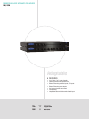
Front Panel Controls and Indicators
Bridge Mode Indicator: Yellow LED illuminates
when the rear-panel Mode Switch is set to the
“Bridge” position.
Ready Indicator: Green LED, one per channel,
illuminates when the channel is initialized and
ready to produce audio output. Indicator is off
when PIP puts the amplifier in standby mode via
the control system.
Signal Indicators: Three green LEDs per chan-
nel indicate the amplifier’s input and output
signal levels.
Signal: input signal is above –40 dBu.
–20 dB: amplifier output is 20 dB below clipping.
–10 dB: amplifier output is 10 dB below clipping.
Clip Indicator: Red LED, one per channel,
illuminates when the channel’s output signal
reaches the onset of audible clipping. The Clip
Indicator also will illuminate during Thermal
Level Control (TLC) limiting or when the input
compressor/limiter is protecting the amplifier
from input overload.
Thermal Indicator: Red LED, one per channel,
illuminates when the channel has shut down,
or is very near shutting down, due to thermal
stress or overload.
Fault Indicator: Red LED, one per channel,
flashes when the amplifier output channel has
stopped operating.
Data Indicator: Yellow LED indicates control
data activity (if the amplifier is equipped with
an IQ-PIP2 module, and connected to a control
system).
Power Indicator: Blue LED indicates amplifier
has been turned on and AC power is available.
The LED will flash when the AC line voltage is
15% above or 25% below the nominal rated
value.
Cooling Vents: Front-to-rear forced airflow.
Power Switch: Push-on / push-off switch.
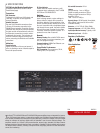
Back Panel Controls and Connectors
Power Cord Connector: Standard 15 amp IEC
inlet. Voltage is indicated above IEC inlet.
Reset Switch: Resets the circuit breaker that
protects the power supply.
Speaker Connectors: One four-pole touch-proof
terminal strip. Accepts up to 10 AWG terminal
forks.
Input Connectors: Balanced 2-pin terminal block
connector, one per channel, on the standard
PIP2-BBY module.
Channel Level Control: One 21-position
detented rotary attenuator per channel, ranging
from minus infinity (–70 dB) to 0 dB gain.
Mode Switch: Two-position switch is used to
select the amplifier’s mode of operation: Dual or
Bridge-Mono.
Highpass Filter: One 3-position switch per
channel selects between OFF, 35Hz and 70Hz
3rd-order filters.
“Y” Input Switch: When set to ON, this switch
parallels the input signals of the two channels
for use when the input signal is mono. Also can
be used to daisy-chain the signal to another
amplifier.
Ventilation Grille: Front-to-rear forced airflow.
Options
PIP2 modules, including the PIP-Lite, PIP-USP3,
and PIP-USP3/CN.
Protection Systems
Thermal Level Control (TLC): If an amplifier
channel starts to overheat, the TLC circuit will
engage the input compressor. By compressing
the input, the amplifier will not generate as much
heat and will have a chance to cool down.
Junction Temperature Simulation (JTS): In the
CTs 600/1200, if excess power is demanded,
JTS circuitry limits the drive level of the output
devices to a safe range, preventing damage.
Fault: The amplifier will light the Fault LED if the
amplifier output stage stops operating.
AC Under-/Over-Voltage Protection: If the AC
line voltage drops below 25% or rises above
15% of the nominal operating voltage of the
amplifier, the amplifier’s power supply turns
off and the blue Power LED flashes. The ampli-
fier will turn back on when the AC line voltage
returns to safe operating levels.
Circuit Breaker: This breaker protects the ampli-
fier from excessive AC current draw.
DC Output Servo: The output servo circuit
protects your drivers by eliminating DC offset,
even in the presence of very large asymmetrical
signals.
In-rush Limiting: A soft-start circuit in the
power supply minimizes the amplifier’s current
draw during power-on.
Variable-speed Fan: Two continuously variable
speed fans direct the airflow through the ampli-
fier for cooling.
Regulatory Certifications
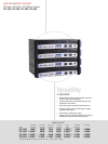
Other Applications
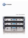
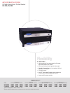
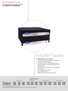
C
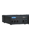
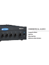
rown’s CTs Series amplifiers provide exceptional performance, flexibility and value for installed
sound applications. CTs Series amplifiers feature independent selection of high and low impedance
operation for a specific channel, plus power levels and features that were carefully chosen to match
the requirements of fixed install design. Easy integration with HiQnet™ and CobraNet™ allows CTs
amplifiers to deliver a comprehensive lineup of monitoring and control features along with digital audio
transport for an award-winning digital audio solution.
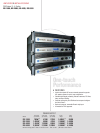
POWER OUTPUT*
2-ohm Dual 4-ohm Dual 8-ohm Dual 16-ohm Dual 70V Dual 100V Dual 4-ohm 8-ohm 16-ohm 100V 140V 200V
Models (per channel) (per channel) (per channel) (per channel) (per channel) (per channel) Bridge Bridge Bridge Bridge Bridge Bridge
CTs 600 150W 300W 300W 300W 300W 300W‡ 300W 600W 600W 600W‡ 600W 600W‡
CTs 1200 250W 600W 600W 300W 600W 600W‡ 500W 1,200W 1,200W 1,200W‡ 1,200W 1,200W‡
CTs 2000 1,000W 1,000W 1,000W 625W 1,000W 1,000W 2,000W 2,000W 2,000W 2,000W 2,000W 2,000W
CTs 3000 1,500W 1,500W 1,250W 625W 1,500W 1,500W 3,000W 3,000W 2,500W 3,000W 3,000W 3,000W
*Maximum average power in watts at rated THD, 20 Hz - 20 kHz. ‡With T-170V or TP-170V.
9/07 136317-2B