Micro-Tech Series Power Amplifiers
page 16
Operation Manual
6.2.1 Stereo Operation
For simplicity, the discussion of Stereo opera-
tion will refer to one channel only. Mono opera-
tion will be discussed later. For specific circuit
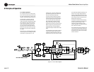
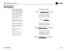
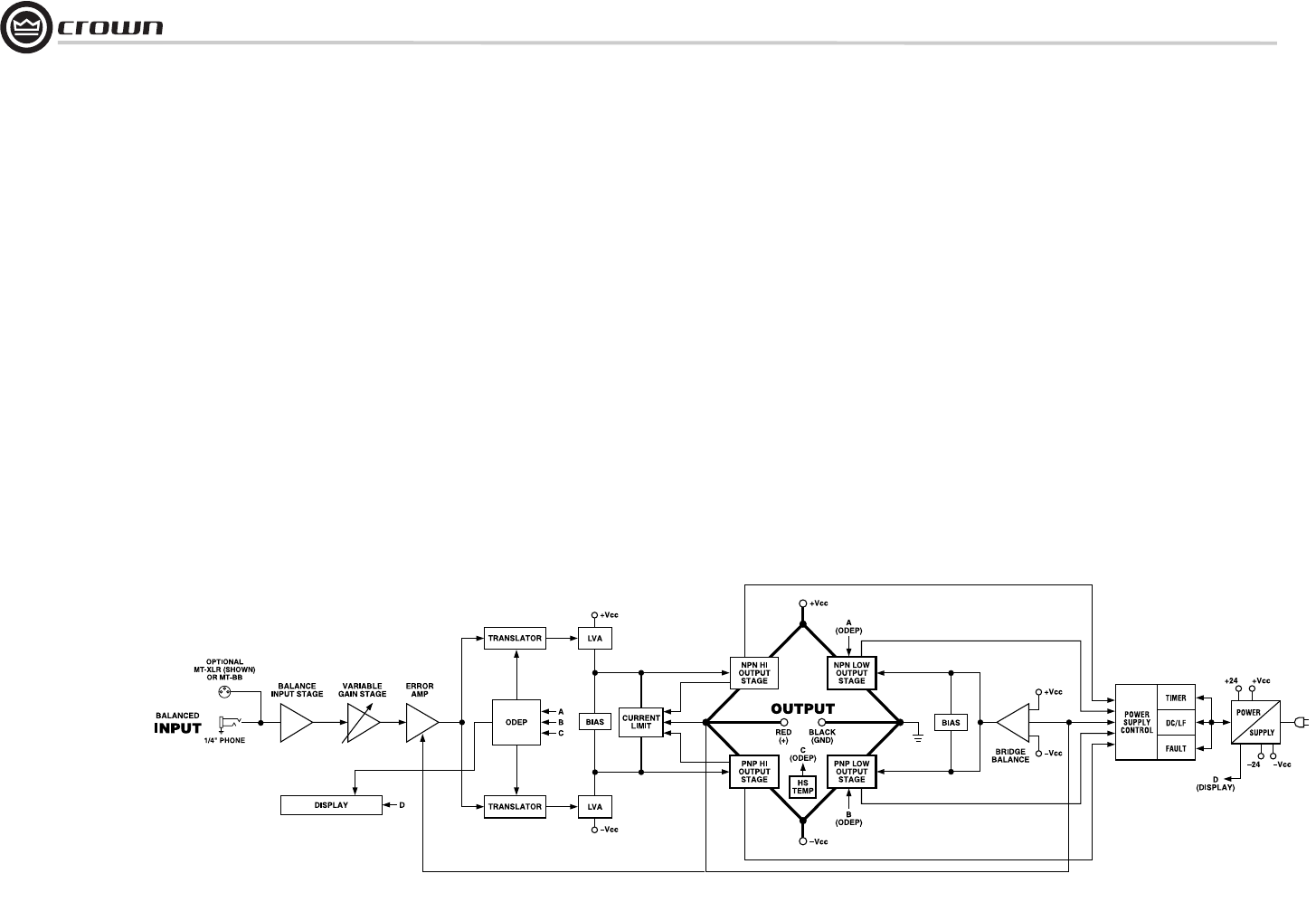
references, see the block diagram in Figure 6.1.
The signal at the ¼-inch phone jack input
passes directly to the balanced gain stage
(U104-A and U104-B). The balanced gain stage
causes balanced to single-ended conversion
using a difference amplifier. From there, gain
can be controlled with a potentiometer. The
error amp (U104-C) amplifies the difference
between the output signal and the input signal
from the gain pot, and drives the voltage trans-
lator stage.
From the error amp, the voltage translator stage
routes the signal to the Last Voltage Amplifiers
(LVAs) based on signal polarity. The +LVA
(Q105) and the –LVA (Q110), with their push-
pull effect through the bias servo Q318, drive
the fully complementary output stage.
The bias servo Q318 is thermally coupled to
the heat sink and sets the quiescent bias cur-
rent in the output stage to lower the distortion
in the crossover region of the output signal.
D301, D302, D303, and D304 remove the
charge on the unused portion of the output
stage based on the polarity of the output signal.
With the voltage swing provided by the LVAs,
the signal then gains current amplification
through the Darlington emitter-follower output
stage.
The bridge-balanced circuit (U104-D) receives
a signal from the output of the amplifier and
compares it to the signal at the Vcc supply. The
bridge-balanced circuit then develops a voltage
to drive the bridge-balanced output stage. This
results in the Vcc supply having exactly one
half of the output voltage added to their quies-
cent voltage. D309, D310, D311 and a trimmer
resistor set the quiescent current point for the
bridge-balanced output stage.
The protection mechanisms that affect the sig-
nal path are implemented to protect the ampli-
fier under real-world conditions. These
conditions are high instantaneous current,
excessive temperature, and output device oper-
ation outside safe conditions.
Q107 and Q108 sense output current and act as
a common current limiter. When instantaneous
current exceeds the design criteria, the limiters
remove the drive from the LVAs to limit output
current to safe levels.
6 Principles of Operation
ONLY ONE CHANNEL SHOWN
Figure 6.1 Circuit Block Diagram


