


Micro-Tech Series Power Amplifiers
page 12
Operation Manual
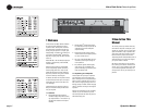
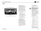
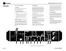
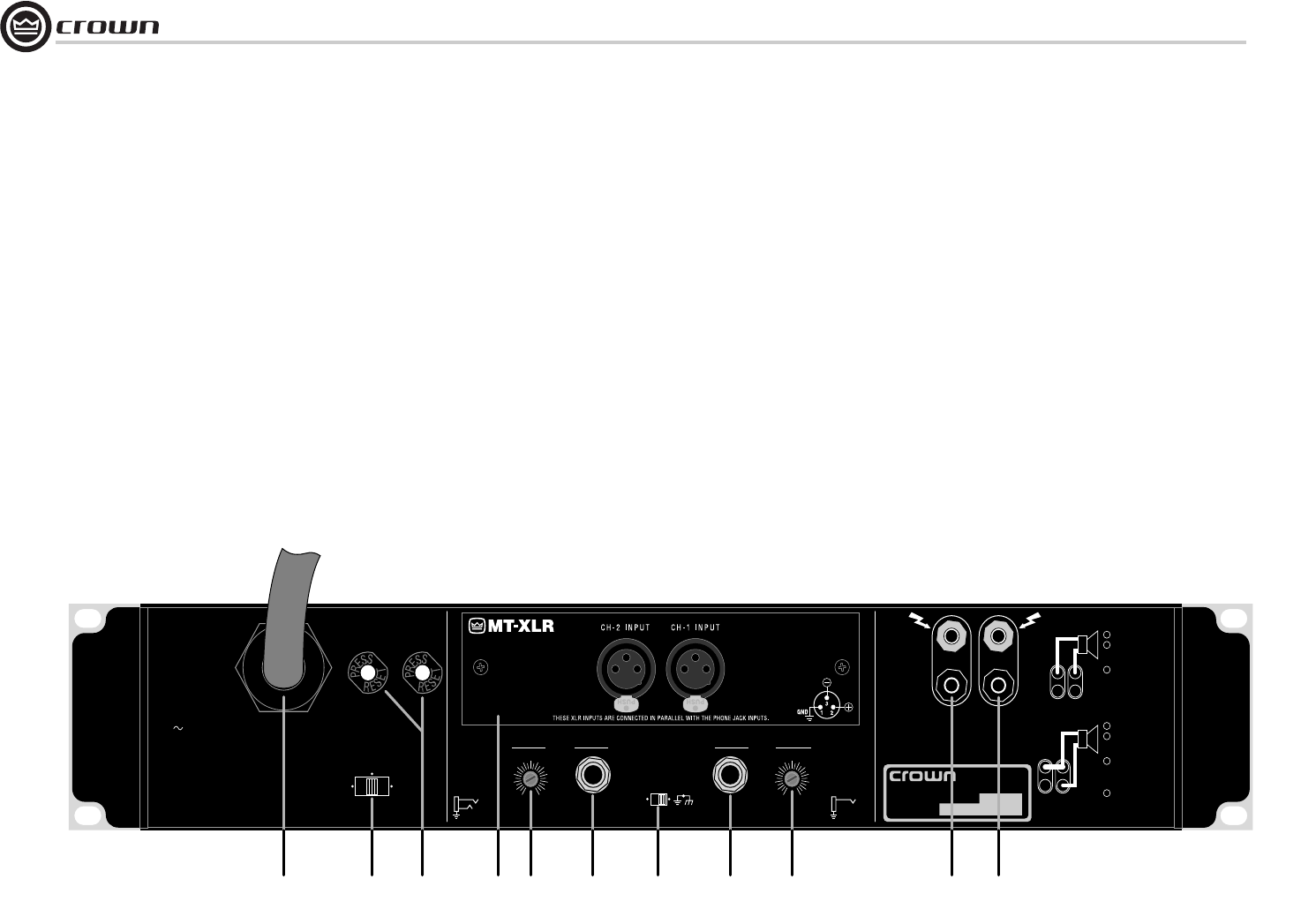
4.2.2 Rear Panel Facilities
F. Power Cord
All units are shipped with an approprate plug and
cord for the required AC voltage.
G. Stereo/Mono Modes Switch
• Use Stereo mode for normal two-channel oper-
ation.
• Use Bridge-Mono mode to drive a single chan-
nel with a load impedance of at least 4 ohms.
• Use Parallel-Mono mode to drive a single
channel with a load impedance less than 4
ohms.
Important: Turn off the amplifier before changing the
Stereo/Mono modes switch.
H. Reset Switches (Micro-Tech 2400 only)
The Micro-Tech 2400 has two push-button reset
swiches on the back panel that are used to reset the
circuit breakers for the high-voltage power supplies.
Refer to Section 5.1.5 in the rare event of a tripped
breaker.
I. MT-XLR Module
This module provides two balanced XLR inputs.
Because the MT-XLR connectors are in parallel with
the amplifier’s built-in phone connectors, an input
signal fed to either input can be fed to another
amplifier from the unused connector for that chan-
nel. If you prefer to use barrier block inputs instead,
order the MT-BB accessory (see Section 5.2).
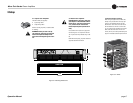
Input Sensitivity Switch
The three-position input sensitivity switch (Figure
4.2) is located inside the amplifier behind the MT-
XLR module (I). See Section 3.7 for details.
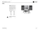
J. Level Controls
Used to set the amplifier's output levels. These con-
trols are on the back panel to prevent tampering. Be
sure to turn down the Channel-2 level control (fully
counterclockwise) when operating in Bridge-Mono
or Parallel-Mono mode.
K. Balanced Phone Jack Inputs
A balanced ¼-inch phone jack input is provided for
each channel. The jacks may be used with either
balanced (tip, ring and sleeve) or unbalanced (tip
and sleeve) lines (refer to Figure 3.5). Balanced XLR
ijnputs for each channel are provided with the
MT-XLR module. Barrier-block input connectors are
available with the MT-BB accessory (see Section
5.2.2). Caution: Do not use the Channel-2 input in
either mono mode.
L. Ground Lift Switch
Used to isolate the phone jack signal grounds from
the AC power (chassis) ground. Moving the switch
to the "lift" position helps prevent the hum associ-
ated with ground loops. Sliding the switch to the left
isolates or "lifts" the grounds by placing an imped-
ance between the sleeve of each phone jack and the
AC ground.
M. Output Jacks
A pair of versatile binding posts is provided for out-
put connection to each channel. Loudspeakers can
be easily connected using banana plugs, spade lugs
or bare wire (European models do not accept
banana plugs). See Section 3.5.
CAUTION:
THIS COVER IS NECESSARY FOR
EFFICIENT COOLING OF THE AMPLIFIER.
REMOVE ONLY TO ACCESS GAIN SWITCH.
0
1
2
3
4
5
6
7
8
9
10
11
12
0
1
2
3
4
5
6
7
8
9
10
11
12
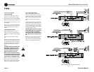
BRIDGE-MONO WIRING
TURN AMPLIFIER OFF.
SET STEREO/MONO
SWITCH TO
BRIDGE-MONO.
OUTPUT ACROSS
RED TERMINALS
ONLY. (CH-1
IS POSITIVE.)
PARALLEL-MONO WIRING
TURN AMPLIFIER OFF.
SET STEREO/MONO
SWITCH TO
PARALLEL-MONO.
ADD JUMPER (14
GAGE OR LARGER)
ACROSS RED
TERMINALS.
OUTPUT ACROSS CH-1
TERMINALS ONLY.
1
2
3
4
1
2
3
CH-2 CH-1
+
–
–
+
INPUT GROUND LIFT
(AFFECTS PHONE INPUTS ONLY.)
CAUTION:
TURN OFF AMPLIFIER
BEFORE CHANGING THIS SWITCH!
STEREO
BRIDGE
MONO
PARALLEL
MONO
CLASS 1
OUTPUT
WIRING
REQUIRED.
WARNING: TO REDUCE THE RISK OF FIRE OR
ELECTRIC SHOCK DO NOT EXPOSE THIS EQUIPMENT
TO RAIN OR MOISTURE.
OUTPUTS
LIFT
REG. U.S. PAT. OFF.
4,330,809
4,611,180
MODEL: MICRO-TECH 2400 SERIES
AC VOLTS: 120 AMPS: 17 60 Hz
MAXIMUM OUTPUT: 900 WATTS
PER CHANNEL INTO 2 OHMS AT 1 KHz
WITH NO MORE THAN 0.1% THD.
UNBALANCED
INPUT WIRING
BALANCED
INPUT WIRING
+
–
TIP
RING
SLEEVE
GND
+
TIP
SLEEVE
GND
CH-2
(MONO)
INPUT
GAIN
CH-1
INPUT
GAIN
THIS AMPLIFIER IS EQUIPPED WITH SELECTABLE INPUT SENSITIVITY. REMOVE COVER PLATE (ABOVE) TO ACCESS SENSITIVITY SWITCH.
®
INTERNATIONAL, INC.
ELECTRONIC EQUIPMENT
ELKHART, IN 46517
MADE IN U.S.A.
SERIAL NUMBER
0000
000000
FGH K KL M MJJ
PUSH TO RESET
I
Figure 4.2 Rear Panel Connectors and Controls
4 Operation