


1 2 3 48105 6 7 119 12 13 14 1615 17 18 19 20 21
FRONT PANEL:
1: INPUT: Connect your guitar here using a shielded
instrument cable.
CHANNEL A: A high gain channel giving you sounds from
a slight edge to serious overdrive.
2: GAIN: Sets the amount of compression and distortion
from the amplifier. At far left, the sound will have a thick
compressed quality. As you turn the control to the right the
amount of distortion increases. Use this along with the
Shape and Level controls (#3 and 7) to create a wide vari-
ety of sounds.
3: SHAPE: Rotate the Shape control until you find the
sound you’re looking for. Turning the control towards the
left enhances the mid frequencies; turning it to the right
enhances the low and high frequencies. Controlled by the
Shape Active switch (#4).
4: SHAPE ACTIVE: Boosts the gain of Channel A and
activates the Shape control (#3). A footswitch (see #29,
rear panel) overrides this switch.
5: LOW: Adjusts the low frequency output level: to the left
reduces the low frequency output; to the right increases it.
This control allows a range of 10dB at 80Hz.
6: HIGH: Adjusts the high frequency output level: to the left
reduces the high frequency output, to the right increases it.
This control allows a range of 10dB at 7kHz.
7: LEVEL: Sets the output volume level from Channel A: in
the far-left position there is no output; turning the control to
the right increases the output. Use this control along with
the Gain and Shape controls (#2 & 3) to create a wide vari-
ety of sounds.
8: CHANNEL SELECT: When this switch is pressed in
Channel A is engaged. Channel B is selected when this
switch is out. A footswitch (see #29, rear panel) overrides
this switch. The adjacent LEDs indicate which channel is
selected.
CHANNEL B: A normal gain channel designed to give you
crystal clear sounds.
9: LEVEL: Sets the output volume level from Channel B:
in the far-left position there is no output; turning the control
to the right increases the output level.
10: LOW: Adjusts the low frequency output level: to the left
reduces the low frequency output; to the right increases it.
This control allows a range of 20dB at 100Hz.
11: MID: Adjusts the mid frequency output level: to the left
reduces the midrange output; turning it to the right increas-
es it. This control allows a range of 14dB at 700Hz.
12: HIGH: Adjusts the high frequency output level: to the
left reduces the high frequency output; to the right increas-
es it. This control allows a range of 27dB at 10kHz.
13: REVERB A: Adjust the amount of reverb for Channel
A with this control: in the full-left position the output signal
is “dry” (no reverb); rotating the control to the right increas-
es the amount of effect.
14: REVERB B: Adjust the amount of reverb for Channel
B with this control: in the full-left position the output signal
is “dry” (no reverb); rotating the control to the right increas-
es the amount of effect.
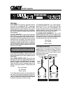
15: INSERT LOOP: Connect an external effects device via
this jack. Use a stereo 1/4” male Y-cord: ring = send, tip =
return, sleeve = ground. See the illustration on the panel to
the right for more information.
16: CHORUS ON/OFF: Turn the Chorus/Expander on and
off with this switch. When the switch is pressed in, the
Chorus/Expander is active. A footswitch (see #28, rear
panel) overrides this switch.
17: CHORUS/EXPANDER: Select between the built-in
stereo chorus or the “expander” circuit with this switch.
When the switch is pressed in, the chorus section is select-
ed. (The yellow LED next to the Depth control, #18, will
glow when the Chorus is selected.) When the switch is out,
the amplifier’s expander circuit is activated, giving the
sound a wide-open, “spatial” effect. In order for either effect
to be active, the Chorus On/Off switch (#16) must be
pressed in.
18: DEPTH: Set the intensity of the chorus effect with this
control: in the far left position there will be almost no cho-
rus; as you rotate the control to the right the amount of
effect increases.
19: RATE: Set the speed of the chorus effect with this con-
trol: to the left for slow, smooth “phasing” sounds, to the
right for faster “vibrato” sounds.
20: POWER LED: Glows when the amplifier is turned on.
21: POWER SWITCH: Turns the amplifier ON in the up
position, off in the down position. The POWER LED (#20)
works with this switch as a visual indicator.
GX-60C Amplifier