


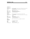
VOLTAGE FUSE TYPE
100V 8 AMP SLOW BLOW 5 x 20mm
120V 8 AMP SLOW BLOW 5 x 20mm
220V 4 AMP SLOW BLOW 5 x 20mm
240V 4 AMP SLOW BLOW 5 x 20mm
FOR CONTINUED PROTECTION
AGAINST SHOCK OR FIRE:
1. REPLACE FUSE WITH SAME
TYPE AND RATING
2. DO NOT EXPOSE THIS UNIT
TO RAIN OR MOISTURE
UNBRIDGED
UNBALANCED
BALANCED
UNBALANCED
BALANCED
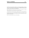
MAIN POWER
OFF ON
AC LINE FUSE CHART FUSE AND VOLTAGE SELECTOR
FUSE VALUE -SEE FUSE CHART
VOLTAGE SELECTION-
SEE OPERATION MANUAL
!
NOTE
SEE SERIAL TAG FOR POWER
REQUIREMENTS, REMOVE POWER
CORD BEFORE CHANGING
FUSE OR LINE VOLTAGE
!
120
AC LINE INPUT
~
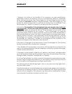
TECHNOLOGIES INC.
MODEL
SERIAL NUMBER
VOLTAGE REQUIREMENT
MANUFACTURED IN THE USA
HZ
POWER REQUIREMENT
VA
TO PREVENT ELECTRIC SHOCK, DO NOT
REMOVE COVER. NO USER SERVICEABLE
PARTS INSIDE. REFER SERVICING TO
QUALIFIED SERVICE PERSONNEL.
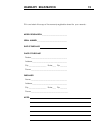
CH 1 OUTPUT CH 2 OUTPUT CH 3 OUTPUT CH 4 OUTPUTCH 1 INPUTS CH 2 INPUTS CH 3 INPUTS
CH 4 INPUTS
UNBRIDGED
CAUTION
WARNING
!
BRIDGED-CHANNEL 1
AND CHANNEL 2
BRIDGED-CHANNEL 3
AND CHANNEL 4
BRIDGED-DO NOT USE GROUNDS BRIDGED-DO NOT USE GROUNDS
DO NOT ALLOW AMPLIFIER OUTPUTS
TO COMMON BETWEEN CHANNELS,
OR CONTACT CHASSIS OR INPUT
GROUNDS, OR TO BE CONNECTED
TO ANY ACTIVE CURRENT SOURCE.
THIS PRODUCT
IS DESIGNED,
ENGINEERED
AND BUILT IN THE UNITED
STATES OF AMERICA.
BRIDGED
INPUT
BRIDGED
INPUT
33122
6 5 4
1
223 3
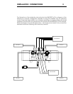
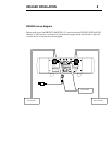
DETAILED INSTALLATION
4
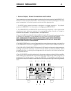
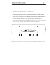
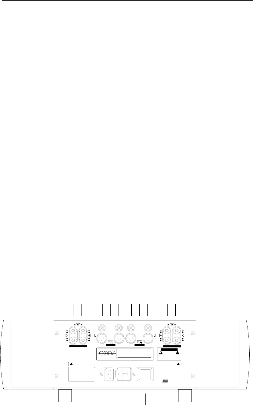
I. Source-Output, Power Connections and Controls
The connectors and controls are clearly marked on the back panel of the AMPLIFIER v10.
Note the correct channel orientation. The function and channel markings on the rear
panel correspond to the front panel controls and their signal paths.
1. The MODE switch selects between unbridged or bridged operation. The default
position is UNBRIDGED. For information on bridging see BRIDGE SETUP.
2. The UNBALANCED and BALANCED inputs should be attached to the appropriate
unbalanced and balanced outputs of a preamplifier either directly or through a
crossover or processor, as appropriate to the application.
3. The CH1 OUTPUT, CH 2 OUTPUT, CH 3 OUTPUT, CH 4 OUTPUT should be attached to four
or three or two speakers. This will depend on how many channels are bridged.
NOTE: THERE ARE NO OUTPUT FUSES SO AS TO INSURE A LOW OUTPUT IMPEDANCE.
SPEAKER PROTECTION IS LEFT TO THE SPEAKER MANUFACTER AS THEY WOULD BEST
KNOW HOW TO PROTECT THEIR SPEAKER.
4. The MAIN POWER switch, once all appropriate connectsions are made, may be left on
as the AMPLIFIER v10 draws a negligible amount of current when the BIAS is turned off.
5. The FUSE AND VOLTAGE SELECTOR houses a 5 X 20 slow blow fuse and voltage selector
cartridge. Should the fuse blow, contact a Coda dealer or call Coda directly. When
changing the fuse, or altering the voltage selection be sure this unit is disconected from
its AC power source.
6. The AC LINE INPUT should be attached to the power cable provided with the amplifier.
After making the appropriate connections insert the three prong safety plug into an
appropriate AC power source. Once the AMPLIFIER v10 is properly connected, the
power switch may be turned on and the led on the front panel will light indicating a ready
state.