


9002 Owner’s Manual •
••
• (V 1.0) Page 11 of 18
Board Installation
Use the following steps to install the card in the openGear
TM
8310 frame:
1. Refer to the Owner’s Manual of the openGear
TM
8310 frame to ensure that the frame
is properly installed according to instructions.
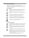
Warning
Heat and power distribution requirements within a frame may dictate
specific slot placement of cards. Cards with many heat-producing
components should be arranged to avoid areas of excess heat build-up,
particularly in frames using convection cooling.
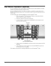
2. After selecting the desired frame installation slot, hold the card by the edges and
carefully align the card edges with the slots in the frame. Then, fully insert the card
into the frame until the rear connection plugs are properly seated on the midplane and
rear modules.
This completes the procedure for installing the card in the openGear
TM
8310 frame.
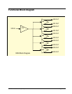
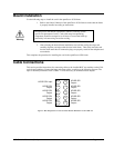
Cable Connections
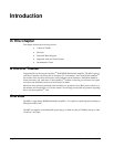
This section provides instructions for connecting cables to the installed BNC rear modules on the 8310
series frame backplane. Connect the input and output cables according to the following diagram. The
input is internally terminated with 75 Ohms. It is not necessary to terminate unused outputs.
Figure 3. BNC Designations for the Card Rear Module RM-9002-A or 8310-RM-100
2
4
6
8
3
5
7
10
9
HD/SD SDI Input
HD/SD SDI
Output
HD/SD SDI
Output
HD/SD SDI
Output
HD/SD SDI
Output
HD/SD SDI
Output
1
HD/SD SDI
Output
HD/SD SDI
Output
HD/SD SDI
Output
HD/SD SDI
Output