


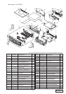
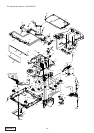

PU-2471A
PU-2472B, C
- 3 -
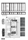
EXPLANATION OF IC
052-1170-13 uPD784216BYGC-110-8EU
CD & Radio System Controller
1.Terminal Description
pin 1: KI 1 :IN: Key scan signal input.
pin 2: KI 2 :IN: Key scan signal input.
pin 3: KI 3 :IN: Key scan signal input.
pin 4: KI 4 :IN: Key scan signal input.
pin 5: KI 5 :IN: Key scan signal input.
pin 6: NU : - : Not in use.
pin 7: NU : - : Not in use.
pin 8: NU : - : Not in use.
pin 9:VDD : - : Positive supply voltage.
pin 10:X 2 : - : Crystal connection.
pin 11:X 1 : - : Crystal connection.
pin 12:VSS : - : Negative supply voltage.
pin 13:NU : - :Not in use.
pin 14:NU : - :Not in use.
pin 15: RESET :IN: Reset signal input.
pin 16:SBSY :IN: Sub code sync input.
pin 17:VAN INT :IN: The interrupt signal input from the VAN
Bus.
pin 18: KI 0 :IN: Key scan signal input.
pin 19:RDS CLK :IN: RDS clock pulse input.
pin 20: RDS DATA :IN: RDS serial data input.
pin 21:BU DET :IN: Backup detection signal input.
pin 22:+VAN DET :IN: +VAN ON signal input.
pin 23:A VDD : - : Positive supply voltage for the Analog sec-
tion.
pin 24:A Vref :IN: Reference voltage for ADC.
pin 25:NU : - :Not in use.
pin 26:FM S METER :IN: The input terminal of Internal A/D convert-
er to monitor the radio field strength for
FM.
pin 27: DIAG PAHAN :IN: Phantom circuit status input.
pin 28:NU : - :Not in use.
pin 29: IF BAND :IN: IF band width.
pin 30:NU : - :Not in use.
pin 31:NU : - :Not in use.
pin 32:MUTE DET :IN: The input terminal of the internal ADC for
sensing the backup voltage.
pin 33:A VSS : - : Analog ground.
pin 34:NU : - :Not in use.
pin 35:NU : - :Not in use.
pin 36:A Vref :IN: Reference voltage for ADC.
pin 37: MISO :IN: The serial data input from the VAN control
IC.
pin 38: MISIO : O : The serial data output to the VAN control
IC.
pin 39:SCLK :O : The clock pulse output to the VAN control
IC.
pin 40:NU : - :Not in use.
pin 41:NU : - :Not in use.
pin 42: A MUTE : O :The audio mute signal output.
pin 43: S SO : O: Slave chip select signal output.
pin 44: BEEP :O : Beep out.
pin 45:SDAT :O : The serial data output to the tuner pack.
pin 46:VAN RESET : O :The reset pulse output to VAN control IC.
pin 47: S CL 1 : O :The clock pulse output for the tuner pack.
pin 48: 12V SW : O: ON signal output to the external power
supply.
pin 49:5V REM : O: ON signal output to the 5V power supply.
pin 50: 14V REM : O :ON signal output to the 14V power supply.
pin 51:+VAN ON : O :+VAN ON signal output.
pin 52: VAN WU : O: The Wake up signal output to VAN-BUS-
IC.
pin 53: TEL MUTE :IN: Telephone mute command input.
pin 54:CD 8V ON : O : ON signal output to the CD 8V power sup-
ply.
pin 55:NU : - :Not in use.
pin 56: S DA CO : O :The serial data output to the CASP IC.
pin 57: S CLK CO : O: The clock pulse output to the CASP IC.
pin 58:NU : - :Not in use.
pin 59:NU : - :Not in use.
pin 60:NU : - :Not in use.
pin 61:NU : - :Not in use.
pin 62:NU : - :Not in use.
pin 63:NU : - :Not in use.
pin 64:NU : - :Not in use.
pin 65:NU : - :Not in use.
pin 66:NU : - :Not in use.
pin 67:NU : - :Not in use.
pin 68:NU : - :Not in use.
pin 69:NU : - :Not in use.
pin 70:NU : - :Not in use.
pin 71:NU : - :Not in use.
pin 72:VSS : - : Negative supply voltage.
pin 73:NU : - :Not in use.
pin 74: CD CHO : O :CD check signal output.
pin 75: CD DET :IN:CD mechanism is connected = "H".
pin 76:No Exp : - : No explanation.
pin 77:No Exp : - : No explanation.
pin 78:No Exp : - : No explanation.
pin 79:No Exp : - : No explanation.
pin 80:No Exp : - : No explanation.
pin 81:VDD : - : Positive supply voltage.
pin 82: DIMMER CNT : O :Dimmer control signal output.
pin 83:No Exp : - : No explanation.
pin 84:No Exp : - : No explanation.
pin 85:No Exp : - : No explanation.
pin 86:No Exp : - : No explanation.
pin 87:No Exp : - : No explanation.
pin 88:No Exp : - : No explanation.
pin 89:No Exp : - : No explanation.
pin 90:No Exp : - : No explanation.
pin 91:No Exp : - : No explanation.
pin 92:VOLAI :IN: Volume control pulse input from the rotary
encoder.
pin 93:VOLBI :IN: Volume control pulse input from the rotary
encoder.
pin 94: VPP : - : Connect to ground.
pin 95: CD 5V ON : O: Power supply control signal output for the
5V power supply of the CD mechanism.
pin 96:AM ON : O: AM ON flag output.
pin 97: KO 0 : O: Key scan output terminal.
pin 98: KO 1 : O: Key scan output terminal.
pin 99: KO 2 : O: Key scan output terminal.
pin100:KO 3 : O: Key scan output terminal.