


Operation/Installation Manual
2
English
DESCRIPTION
The APX290M and APX490M use an unregulated MOSFET power supply for
superior sound and output wattage. In addition, a toroid-coil is used to transfer
power with minimal performance loss due to heat. To avoid unwanted noise, a
double-sided conformal printed circuit board with strategically placed compo-
nents keeps AM RFI subdued.
All of the connections and controls for the APX290M and APX490M are conve-
niently located at the ends of the amplifier and labeled appropriately. To ensure
the best possible electrical connections, the power, speaker, and RCA inputs
are gold-plated. An additional benefit of the APX490M is the ability to create a
2, 3, or 4 channel amplified system with a flip of a switch (see Application sec-
tion). In the event of component failure or a short circuit, the APX290M and
APX490M incorporate safe guards and outboard ATC fuses to prevent damage
to the amplifier.
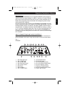
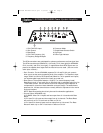
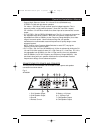
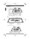
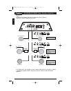
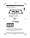
INPUT CONNECTIONS AND AUDIO CONTROLS
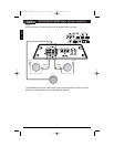
The front panel of the APX490M and APX290M contain both connections for
RCA and speaker level inputs, along with the audio controls as shown below.
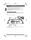
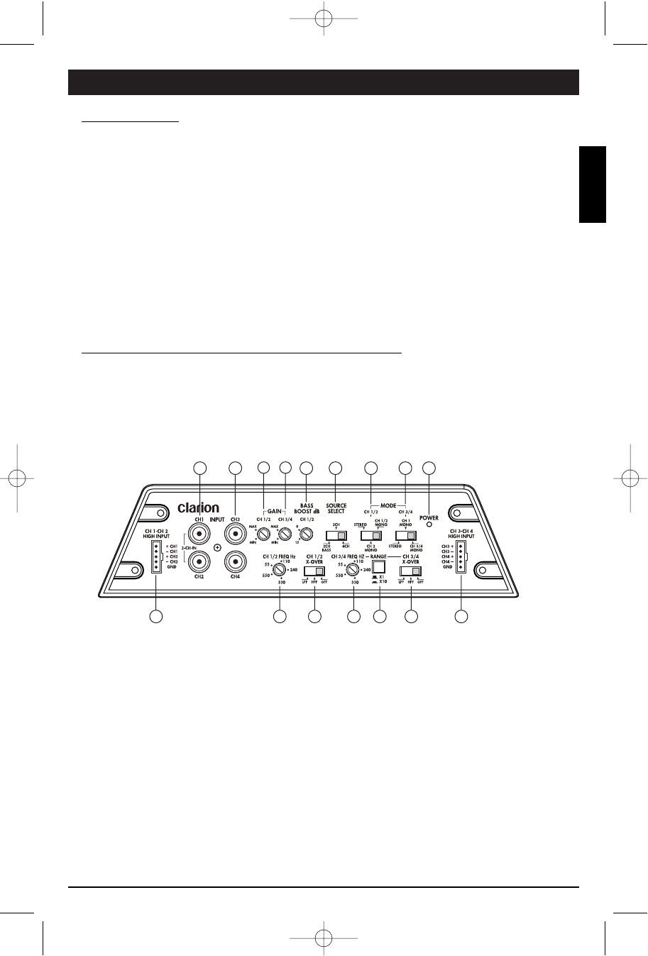
Fig. 1
APX490M
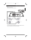
1. CH1/CH2 High Input
2. CH 1/2 RCA Input
3. CH 3/4 RCA Input
4. CH1/CH2 Gain Control
5. CH 3/4 Gain Control
6. Bass Boost
7. Source Select
8. CH 1/2 Mode Switch
9. CH 3/4 Mode Switch
10. CH 3/4 High Input
11. CH 1/2 Frequency Control
12. CH 1/2 Crossover Mode Switch
13. CH 3/4 Frequency Control
14. Frequency Range Multiplier
15. CH 3/4 Crossover Mode Switch
16. Power Light Indicator
1 1011 12 13 14 15
2 3456 7 8 916
APX280M APX490M manual.qxd 2/6/2008 11:38 AM Page 3