Understanding Digital CATV/CATV Modems
Due to the launch of digital CATV across the United States there
is a need for clarification of digital CATV, which Channel
Vision
TM
offers a basic understanding of. Analog channels start
from channel 2 to around the 70’s, digital may start around mid
80’s to as high as 115, some as high as 135. Exclude 95 to 99,
(the old FM band now used for pay-perview or other
programming). Compression of channels will vary in ratio, one
cable company may use 8 to 1 ratio, compressing 6 to 12 or as
high as 16 channels every 6MHz or every channel. The
compressed channels, or forward feed of information is introduced
to the digital to anolog CATV converter box supplied by the
CATV company. This converter box creates hundreds of
channels. The digital forward feed to the converter box must
remain Undisturbed. This means if an incorrect low pass filter is
installed or a modulated channel is placed on top of the digital
information, it will disable the digital converter box. We must
understand frequency allocation to prepare for profitable
installations. Satellite frequency starts at 950 MHz, CATV
systems are maxed at 750MHz and very few are at 860MHz. The
dBmV signal characteristics are opposite from the typical analog
signal, remember the FCC standard is 0dBmV minimum and
15dBmV maximum at the TV. The digital converter’s optimum
level is 0dBmV to-10dBmV analog and drop out levels are -
18dBmV.
Every system will vary, you would need a true digital meter to
read digital, though an RF meter will tell you analog
measurements. The analog signal will vary anywhere from -
30dBmV to -10dBmV. An RF amp may be required for
multiple converter boxes due to the level from the cable
company brought into a residence as low as –30 dbmv.
Modems also have a low analog dBmv requirement. The
analog signal may be too hot for the modem. CATV
companies may use taps in a line to pad down signal;
optimum levels will vary from 0dB to
- 10dB, +10dB may be to hot. Some CATV companies use
channel 106, and of course if the incorrect filter is used it
will disable the modem as it would the digital CATV box.
The modem is usually dedicated at the front end of the
distribution system. Usually a two way splitter with one leg
for modem and the other leg for distribution. CATV
companies are still testing the water with digital cable
converters and modems. A resident may have a modem, a
TV, and various splitters off of one line and be trouble free,
while the neighbor a block away has no equipment other
than a modem and a TV off of separate lines and has drop
out failure; return path seems to be the biggest issue. Some
CATV companies have found that high value hard line taps
are causing modem failure. System specifications of the
CATV system you are installing in is the key to a successful
installation.
Systems With Digital CATV
Now that we have somewhat of a understanding of digital, let’s
work around the digital converter. For years
Channel Vision
TM
has always suggested 2-RG-6 coax to each TV
location for good reason; you can dedicate the
digital converter or modems and use the other coax for
distribution/modulation/satellite/antenna/CATV cable ready.
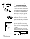
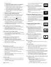
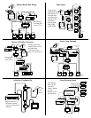
*Please see diagram A on the next page
If you only have one coax to each location, of course your options
are not as open as having two coax to each location. We can still
modulate with a limited amount of space. Channel Vision
TM
has
created a 3202 low/high pass filter combo. This filter will pass all
channels below 70 and 80 and above, allowing two channels to
modulate.
Channel Vision also has low/high pass in a single filter part #
3205-60/69. This filter has a 4 channel slope on both sides
allowing 2 channels to modulate 64-66. The 3205-70/79 filter
also allows two channels 74-76.
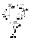
*Please see diagrams B and C on the next page
Channel Vision has also created a 3102-118 low pass filter to add
to the existing line of low pass filters.
The 3102-118 will pass all forward digital information with a 4
channel slope allowing 2 channels of modulation or more
depending on the TV’s tuner capability.
*Please see diagram C on the next page


