


6
Cerwin-Vega! CVP-2153 & CVP-1152 Loudspeaker Systems
Powering Up
To avoid damage to your speaker and other parts of your system, when you turn On your system, always turn On
the power amp last! This will avoid loud, damaging pops that will annoy your audience, and blow your speakers.
When you power down, the amplifier should always be turned Off first to avoid the same problems.
Polarity
When using two or more speaker systems, be sure to match the polarity (+/-) of the speaker system connectors
to those of the amplifier. If polarities do not match, the sounds produced by the speaker will interfere with each
other, making it impossible to achieve a well-balanced sound field.
Hearing damage and prolonged exposure to excessive SPL
CVP Series loudspeakers are easily capable of generating sound pressure levels (SPL) sufficient to cause
permanent hearing damage to performers, production crew, and audience members. Proper precautions should
be taken to avoid prolonged exposure to SPL in excess of 85 dB.
4. SET UP AND USE OF THE CVP-2153 AND THE CVP-1152
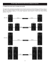
Input Configurations / Full Range and Bi Amp Modes
The CVP Series models are equipped with both a 4-pin Speakon connector and two 1/4” phone jack inputs. The
speakers provide FULL RANGE mode where one amplifier signal powers the entire speaker or BI AMP mode
(Speakon only) where one amplifier signal powers the high frequency compression driver and a second
amplifier powers the low frequency driver(s).
The 4-pin Speakon connectors are configured as follows:
- FULL RANGE mode: 1+ positive / 1- negative. (2+ and 2- are not used)
- BI AMP mode: 1+ LF positive / 1- negative, 2+ HF positive / 2- HF negative.
The quarter inch phone jacks are configured as follows:
- FULL RANGE mode only: Tip positive / Sleeve negative.
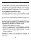
To change the system to Bi Amp mode follow these directions:
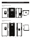
1. Remove the grill (twelve screws) and woofer (eight screws) NOTE: Woofer connection polarity.
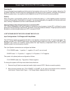
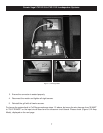
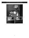
2. Move the wire harness from “FULL RANGE” to “BI AMP” on the input circuit board and the crossover
circuit board. Please check (Figure 1, Full Range Mode), displayed on the next page.