


2
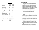
SPECIFICATIONS
Forward Reverse
Frequency Range 54-860 MHz 5-40 MHz
Gain 38 dB typical -1.5 dB (+18 dB) typical
Flatness ±1 dB ±1 dB
Gain Control Range 20 dB 10 dB
Slope Control Range 18 dB 10 dB
Return Loss
Input 8 dB 14 dB
Output 8 dB 14 dB
Noise Figure 9 dB 9 dB
Output Level 40 dBmV 35 dBmV
Composite Triple Beat (CTB) -46 dB*
Cross Modulation (X-Mod) -43 dB*
Second Order Intermodulation -52 dB*
Hum Modulation -65 dB @ maximum gain
Test Ports -30 dB
External Fuse 5 x 20mm 0.35A, 250V
Internal Fuse 5 x 20mm 1.0A, 250V
Operating Temperature Range -10°C to +60°C
Power Requirements 117 VAC 60 Hz 220 mA
Size 8.75” x 7” x 2.625”
Weight 5 pounds
*with 129 channel loading
7
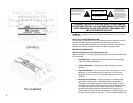
SETUP / OPERATION
1. The amplifier is supplied from the factory with the passive reverse
module installed. For active reverse, see installation on next page.
2. The amplifier has a forward bandwidth of 54-860 MHz with a maximum
of 40 dB gain.
3. The optimal input level for proper amplifier operation and to meet
specifications is 0 to 20 dBmV.
4. The optimal output level for proper amplifier operation and to meet
specifications is 30 to 46 dBmV.
5. The optimal levels for return path is input 3-18 dBmV, and output 20-35
dBmV* (*when reverse amplifier option is used).
6. The input slope control is used to equalize the input signal.
7. The gain control is used to adjust the output level of the amplifier.
8. The second slope control is used to adjust the slope or tilt of the output
of the amplifier.
9. The reverse slope and gain control perform the same functions on the
return path when the reverse amplifier module is utilized.
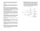
INSTALLATION OF ACTIVE REVERSE MODULE TDA-RA84
1. Unplug amplifiers and remove input & output cables and terminators on
test points.
2. Remove the 8 Phillips head screws holding front cover on.
3. Loosen the 10 Phillips head screws holding the end covers on and lift
off front cover.
4. Remove all 3 / 8-32 nuts and washers on the F ports.
5. Remove the loosened Phillips head screws holding the left end cover on
and remove cover.
6. Unplug the power cable connecting the forward amplifier module to the
power supply P.C. board.
7. Gently lift out the two amplifier modules from the housing.
8. Separate the two modules and set the passive reverse module aside.
9. Carefully line up the connectors on the amplifier module with the
connectors on the reverse amp module and press the two modules
together.
10. Reinstall the modules back in the housing reversing the procedure used
for removing. (Note: Be Sure to Plug in the Amplifier Module Power
Cord).
11. Tighten down all screws and nuts with a screwdriver and wrench.
12. Install reverse amplifier label (supplied with reverse amp module) on
front cover, lining up the holes in the label with the holes in the cover.