


CONTROLS AND DISPLAYS
Never make or break connections to the SA-200.2 unless the SA-200.2 and all
associated components are powered off.
Do not connect the outputs of the SA-200.2 to the outputs of other amplifiers.
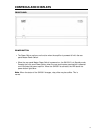
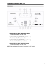
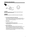
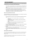
5. LEFT AND RIGHT SPEAKER OUTPUT CONNECTORS
Provide audio output for the speakers. Output connectors can accept bare speaker
wires or most spade and banana connectors. When using bare speaker wires, loosen the
connector, insert the wire into the receptacle, and tighten the connector. The same
procedure should be used for spade connectors.
6. FUSE HOLDER
Use only 8A (120v) or 4A (240v)
7. AC POWER CONNECTOR/ MAIN POWER SWITCH
Connect to AC mains using the included power supply cord. Turn the main power
switch on before use.
8. REMOTE TRIGGER INPUT
Enables the SA-200.2 to be controlled by an external device with a 3.3V DC
minimum to 24V DC maximum trigger output. Connect the trigger output of the external
device to the TRIGGER INPUT of the SA-200.2 power amplifier. The SA-200.2 will
automatically respond when the external device is powered on and off. When the
controlling device is turned on, the amplifier will turn on after a delay. This delay is
intentional and serves to protect the speakers while the unit stabilizes. During start-up,
you may hear a relay clicking. This is normal.
10