


C37
P3
P4
14
J14
P5
P6
2 1
RP2
J15
J16
RP1
J1
U5
U4
ADD THIS JUMPER TO
ACTIVATE THE CH2
CLIPPING ELIMINATOR
STEREO/MONO
SWITCH
CH2 LEVEL
BYPASS
CH1 LEVEL
BYPASS
ADD THIS JUMPER TO
ACTIVATE THE CH1
CLIPPING ELIMINATOR
Servicing Instructions
CAUTION: To reduce the risk of electric shock, do not perform any servicing other than that contained in the
Operating Instructions unless you are qualified to do so. Refer all servicing to qualified service personnel.
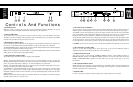
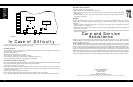
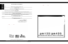
Stereo/Mono Switch
The Stereo/Mono Switch is located on the amplifier’s main circuit board (see Figure 8) and accessible from the back
panel. Leave the switch centered for normal stereo operation, move it to the left for Bridged Mono operation, and
move it to the right for Dual Mono operation.
Level Defeat Jumpers
The Level controls can be bypassed by moving the jumpers for CH1 and CH2 (J15 and J16), which are located on
the amplifier’s main circuit board near the level adjustment pots (see Figure 8). This will lock the amplifier into full
gain (as if the Level pots were fully clockwise).
Input Sensitivity Modification
The input sensitivity of the amplifier is set at the factory to 1.5VRMS for rated output. To increase the sensitivity by
6dB to 0.775VRMS, install jumpers JP1 (CH1) and JP11 (CH2). Sockets for these jumpers are located on the
amplifier’s main circuit board (see Figure 9).
Input Polarity
The XLR input connectors on the pm125/pm420 are shipped from the factory with pin 2 hot (+), as indicated on the rear
panel. The polarity of the balanced inputs can be reversed by changing four jumpers located on the amplifier’s main circuit
board. Crosswire JP3 and JP4 to change the input polarity of CH1 and crosswire JP101 and JP102 to change CH2 (see
Figure 8).
Clipping Eliminator Activation
The clipping eliminator circuit can be activated by installing jumpers in sockets JP9 (CH1) and JP6 (CH2) (see Figure 8).
Figure 8
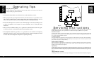
Operating Tips
Using the pm125 /pm420
Once the amplifier has been installed and wired into the system, you are ready to use it. Here are
some tips to help you get the most from it.
• Verify that the Stereo/Mono switch has been set to the mode that you want.
• When you power the system up for the first time (out of the carton), it’s a good idea to start
with all of the amplifier level controls turned down, then advance them slowly, one at a
time, so that you can confirm that each amplifier channel is operating normally.
• Be sure that the Input Level controls are set sufficiently high to allow the preceding device
to drive the amplifier to full output. For most installations, this is wide open (fully
clockwise).
• Once you have established settings, it is a good idea to mark them down, either on paper,
or on pieces of tape or sticky-dots attached to the amplifier’s panel.
• In bi-amplified (multi-amp) systems, it is a good idea to start with the low-frequency
amplifiers turned off or down, and to check each frequency range from highest to lowest
to ensure that each loudspeaker component is operating correctly.
16 1717