


SA-500 Installation and Operating Instructions Page 3
CP4836A 9/14/01
GENERAL DESCRIPTION
The SA500 Siren Amplifier is a premium unit designed for single or dual 100W speaker use. The
primary operating modes are Yelp, Wail, Standby and Radio. A Noise Canceling PA Override and
push-button Horn Override are available in all modes except Radio. A push-button is provided for
push-on/push-off Phaser operation in the Yelp and Wail modes, and Manual siren control in the
Standby mode. The Phaser function can be optionally replaced by Two-Tone or disabled entirely
with program jumpers. Another option allows cycling through Wail, Yelp, Phaser and Standby by
pressing the horn ring when the function switch is in the Standby position (Horn Ring Cycler).
Latching siren cutout input is provided for connection to a door switch, etc. to disable the siren
when exiting the vehicle. Radio and PA volume controls are provided on the front panel. The
front panel is backlighted with LED's for night visibility. This compact unit utilizes short circuit,
high voltage, and reverse polarity protection systems for maximum service life.
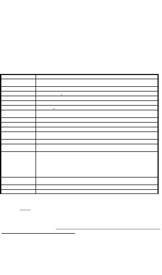
SPECIFICATIONS
Input Voltage 9 - 16 VDC (negative ground)
Input Current 8.0 AMPS (@14.0 VDC - single 100W speaker)
16 AMPS (@14.0 VDC - dual 100W speakers)
Standby Current Less than 200 ma
Audio Frequency 200Hz - 10 kHz + 3db
Audio Distortion Less than 3% (@1 kHz - single 100W speaker)
Audio Output 40 watts (@14.0 VDC - single 100W speaker)
Audio Input 400 ohms + 10%
Output Power 105 WATTS RMS MAX. (15.0 VDC - single 100W speaker)
180 WATTS RMS MAX. (15.0 VDC - dual 100W speakers)
Siren Frequency 700Hz - 1450Hz (Two-Tone and Horn = 435 & 585Hz)
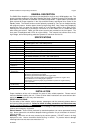
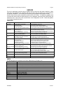
Tones / Cycle Rates Horn Wail Yelp Phaser Two-Tone
Cycle Rates 109 CPS 15 CPM 210 CPM 15 CPS 60 CPM
High Voltage
Protection
16 - 18 VDC will cause siren output to cease, resume at normal
Short Circuit Current 50 AMPS (supply circuit must be capable of supplying this)
Operating
Temperature
-15° F to +140°F
Controls 4-position rotary mode switch (Yelp, Wail, Standby and Radio).
Momentary push-button Horn switch.
Momentary push-button Manual/Phaser toggle switch.
Auxiliary input connection jumper-programmable for positive or negative Horn,
Manual/Phaser or Horn Ring Cycler operation.
Cutout input connection jumper-programmable for positive or negative latching
cutout operation.
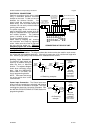
Connections
(10-Pin Conn)
(2) Positive, (2) Negative, (2) Speaker, (2) Radio, Cutout, Auxiliary
Size 6-1/8" Wide, 5-7/8" Deep, 2-1/8" High
Weight 4-1/2 LBS.
INSTALLATION
Proper installation of the unit is essential for years of safe, reliable operation. Please read all
instruction before installing the unit. Failure to follow these instructions can cause serious dam-
age to the unit or vehicle and may void warranties.
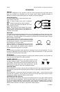
SAFETY PRECAUTIONS
For the safety of the installer, vehicle operator, passengers and the community please observe
the following safety precautions. Failure to follow all safety precautions and instructions may
result in property damage, injury or death.
Qualifications - The installer must have a firm knowledge of basic electricity, vehicle electrical
systems and emergency equipment.
Sound Hazards - Sound levels produced by attached speakers can cause permanent hearing
loss. Never operate this unit without adequate hearing protection for you and others in the area.
(OSHA 1910.95)
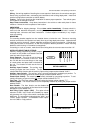
Mounting - Mount the unit for easy access by the vehicle operator. DO NOT mount in air bag
deployment area. Assure clearances before drilling in vehicle. To prevent internal damage
mounting bolts must not enter case more than 1/4".