


TB0329B Page 4 of 7 10/18/03
ELECTRICAL CONNECTIONS
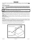
Disconnect vehicle battery before making any electrical connections.
Electrical connections to the amplifier are made using the wiring harness supplied. If the amplifier needs service the
connector can be easily removed without unwiring the harness. The power supply for the amplifier must be capable of
delivering peak currents up to 50 amps for adequate short circuit protection and reliable operation. The preferred
source is directly at the vehicle battery. A fuse on the unit protects from overload.
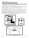
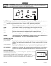
Wire Size and Termination - The diagram shows the minimum wire size used for each connection. If the wire is
longer than 10 ft. use the next larger wire size. Use only high quality crimp connectors for installation on the vehicle.
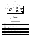
Negative Connection (Black) - Connect to negative battery connector or high current buss.
Positive Connection (Red) - Connect to positive battery connector or high current buss. A power relay may be used.
Speaker Connection (Brown) - Both leads must be used. Connect 1 lead to each terminal or lead of the speaker.
Optional Radio Input Connection (Blue) - Connect 1 lead to each terminal of the radio speaker or output connector.
The input is isolated and polarity is not important. May need to set RADIO VOLUME ADJUST inside the unit.
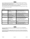
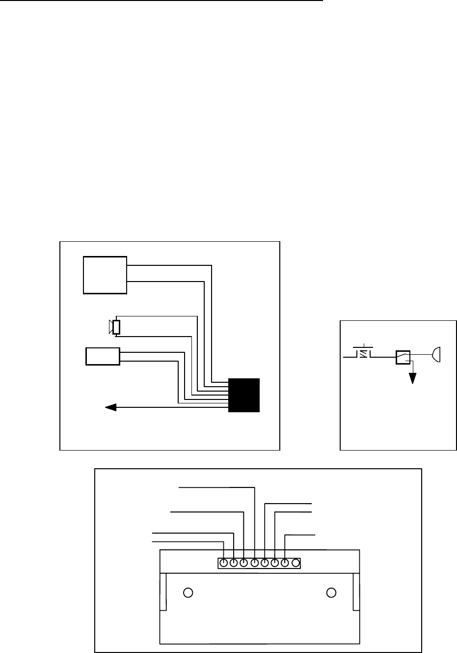
Optional Auxiliary Input Connection (White) - The Auxiliary Input allows an external source to activate the Siren
push button function. The diagram shows a horn ring connection example. Activated by positive or negative input.
NOTE: Permanent disconnection of the vehicle horn is NOT recommended.
W
IRING HARNESS
CONNE
C
TIONS
(2)
#18 AWG BRN
#18 AWG WHT
(2) #18 AWG BLU
Connect to output
j
ack, terminals or
speaker of radio
#14 AWG RED
Extend with #12
#14 AWG BLK
Extend with #12
RADIO
+
BAT
-
A
UX
CP3886
CABLE
HORN RING
CONNECTION
HORN
RING
SWITCH
A
UX
A
dded
SPDT
Switch
HORN
BLUE TO TWO
WAY RADIO SPKR
BLACK TO -VDC
BROWN
TO SPKR
RED TO +VDC
WHITE TO AUX
SIREN SWITCH