


Notas
7
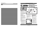
Instrucciones para operar
(Continuación)
IMPORTANTE: Lea estas
instrucciones antes de operar
el compresor o podría dañarlo.
1. Coloque el presostato en “off” y
conecte el cordón eléctrico al
tomacorrientes (Fig. 6).
2. Coloque el presostato en “auto”
para operar la unidad (Fig. 6).
3. Gire la perilla del regulador
completamente en sentido contrario
a las agujas del reloj. El compresor
alcanzará la presión máxima fijada
de fábrica y se apagará.
4. Conecte el extremo de la manguera
a la perilla del regulador. Gire el
regulador en sentido horario para
aumentar la presión que sirve la
herramienta que está usando.
Este
pre-
sostato debe estar en OFF cuando vaya
a conectar o desconectar el cordón
eléctrico del tomacorrientes
AVISO
Instrucciones Adicionales
A
U
T
O
/
O
F
F
Figura 6
CW301300AJ, CW301400AJ
MANUAL
New Switch Installation
(Continued)
in kit. Insert motor and line cord
into switch. Tighten strain relief
clamp screw to hold cords securely.
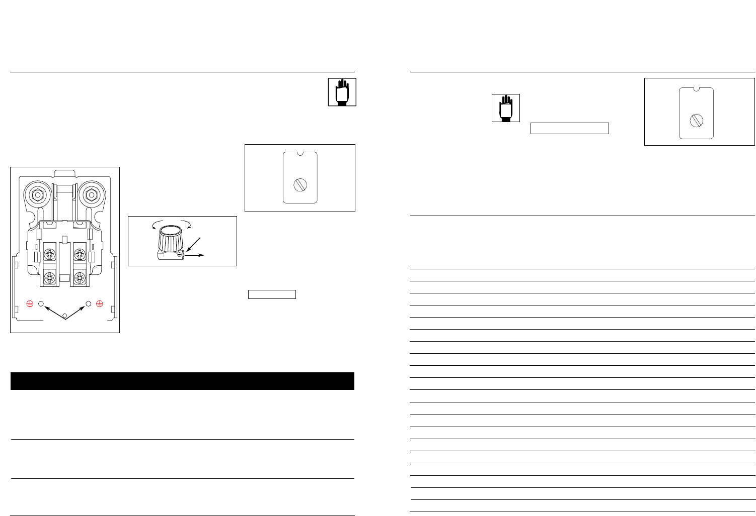
8. Position black motor wire
underneath screw head #4 (See Fig.
4), then tighten screw to secure
wire. Position black line wire
underneath screw head #3, then
tighten screw to secure wire.
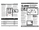
1 Bushing Reducer ST071407AV 1
2 Strain Relief Clamp (ST/SJT) CW209500AV 1
Strain Relief Clamp (SJT/SJT) CW209600AV 1
3 ASME Safety Valve (140 psi) (CW301300AJ) V-215100AV 1
ASME Safety Valve (115 psi) (CW301400AJ) V-215102AV 1
4 1/4" Nipple HF002401AV 2
5 Pressure Gauge GA016302AV 2
6 Unloader Valve CW210000AV 1
7 Pressure Switch (CW301300AJ) CW211200AJ 1
Pressure Switch (CW301400AJ) CW213100AJ 1
8 Regulator RE206203AV 1
9 Quick Connect ST081301AV 1
10 Unloader Tube ST117803AV 1
11 Clamp Screw ST209800AV 1
12 Ground Screw ST074407AV 2
Ref.
No. Description Part Number Qty
2
Additional Operating Instructions
Replacement Parts List - See Figure 2
9. Position white line wire underneath
screw head #1, then tighten screw to
secure wire. Position white motor
wire underneath screw head #2,
then tighten screw to secure wire
(See Fig. 4).
10.Attach green ground wire from line
cord to inside of pressure switch
with ground screw provided in kit.
Repeat procedure with green
ground wire from motor cord. (See
Fig.4
11.Place cover on pressure switch and
tighten cover screw.
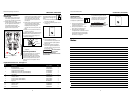
12. Screw regulator onto pressure switch.
NOTE: Ensure air flow indicator arrow
on regulator body points away from
compressor (See Fig. 5).
13. Attach outlet pressure gauge to
regulator.
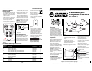
Operating Procedure
In the AUTO position, the compressor
pumps air into tank. It shuts off
automatically when unit reaches its
maximum preset pressure. In the OFF
position, the pressure switch cannot
function and the compressor will not
operate.
IMPORTANT: Read
instructions before operating
compressor or damage may
result.
1. Turn switch to OFF position and plug
in power cord (Fig. 6).
2. Turn switch to AUTO position to run
unit (Fig. 6).
3. Turn regulator knob fully
counterclockwise. Compressor will
build to maximum preset pressure
and shut off.
4. Attach end of hose to regulator
knob. Turn regulator clockwise to
increase pressure going to the tool
that is being used.
This switch should
be in the OFF
position when connecting or
disconnecting the power cord from the
electrical outlet.
NOTICE
Air Flow
Hose
Outlet
Figure 5
MTR
MOTOR
LINE
LINE
1
2
3
4
Figure 4
MANUAL
www.chpower.com
A
U
T
O
/
O
F
F
Figure 6
CW301300AJ, CW301400AJ
Ground terminals