


4 OPERATION
USER MANUAL
VORTEX 6, 4, 2.6 and 200V
P.18
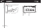
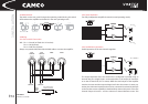
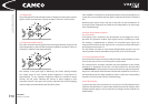
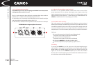
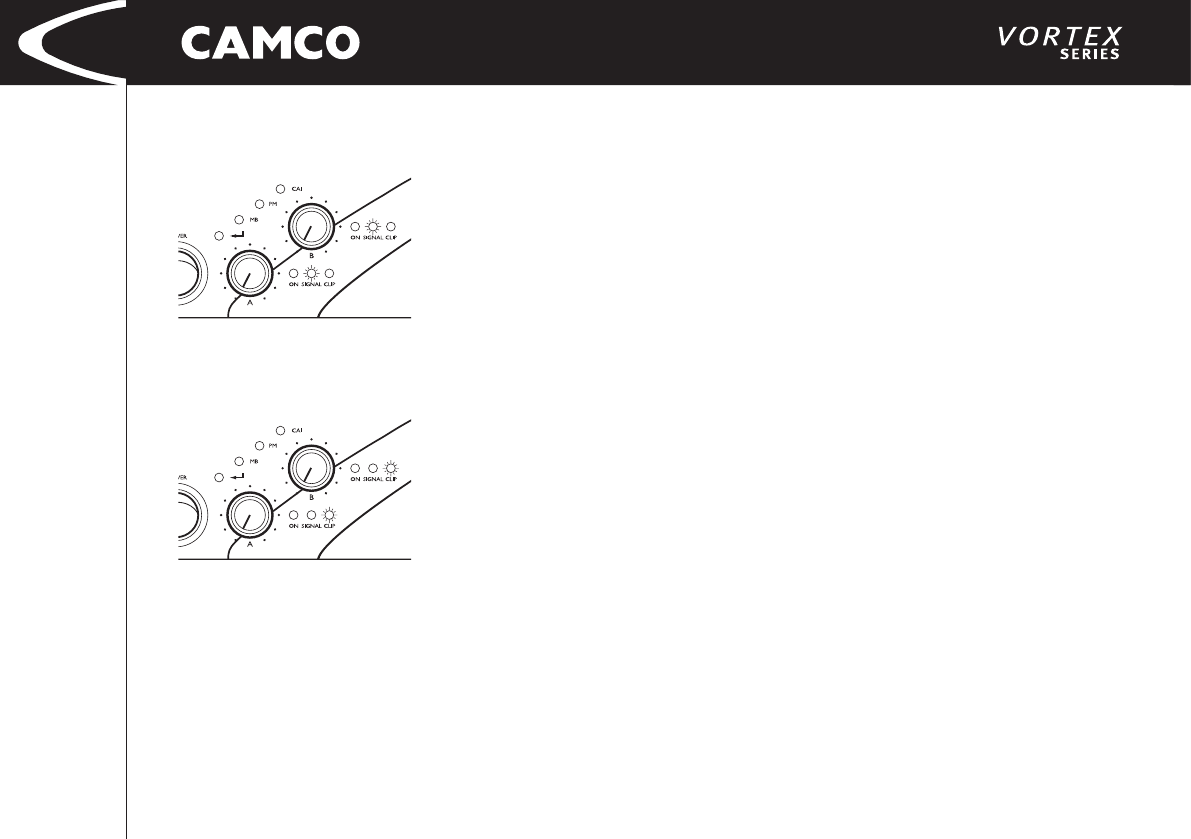
4.2.2 Signal LEDs
The green Signal LED is illuminated when the voltage level at the output reaches
approx. 4 V; this corresponds to a power of approx. 4 W over a 4 Ohm resistor.
4.2.3 Clip LEDs (multifunctional)
The colour of the bi-coloured (green/red) LED changes between red, green and
yellow depending on the load and the signal modulation conditions. (Yellow is
created by a mixture of red and green light).
The intensity of the green light is defi ned by the current passing through
the output stage of each channel (lowest brightness is proportional to
approximately 1 A, the maximum brightness refl ects the maximum output
current). The red colour indicates the amount of signal clipping in each
respective channel. If the green LED (current indicator) and red LED (clipping
indicator) light up simultaneously, the Clip LED is yellow.
If the amplifi er is overdriven for prolonged periods, the Clip LED will appear red
to alert the user more effectively (the green component of the LED is switched
off).
Monitoring the output current and clip via the LEDs can aid the detection of
incorrectly wired components and faults in the loudspeakers at an early stage.
(See 6 Troubleshooting)
4.3 Power Amp Protection Systems
4.3.1 Clip Limiter
If the power amp is overdriven, the clip detection circuit triggers the micro-
processor. The processor reduces input signal level by controlling the DCA.
The strategy is implemented in software. For sinusoidal input signals the
microprocessor limits the input signal in such a way that non-linear distortions
of the signal never exceed 1 %.
The Clip Limiter can work on each channel independently (except in the two
mono-operation modes). To disable the Clip Limiter, see 4.1.4 Limiter Switch.
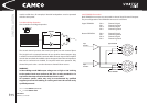
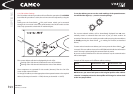
4.3.2 Under Impedance Limiter
As a result of incorrectly connected or defective loads, under impedance or even
short circuits may occur in one or both power amp channels.
The microprocessor constantly calculates the load impedance at the output
channels. If an impedance of less than 1,33 ohms/channel (2,7 ohms/channel
for VORTEX 200V) is detected, the microprocessor limits the signal to the power
amp until a subsequent measure ment indicates that impedance has risen to a
safe level. Whenever the Under Impedance Limiter is active, the corresponding
channel’s On LED is turned off. (See 6 Troubleshooting)
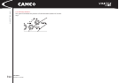
4.3.3 SOA Protection
To ensure that the power transistors are only used in the Safe Operation Area
(SOA), the SOA-protection in stereo mode switches back the rail voltages of the
respective power stage. In mono modes the rail voltages of both channels are
switched back.