


On Off
Loop OutputInput
Balanced Audio - Right Unbalanced
Audio - Right
Input
Loop Output
Input
Loop Output
Out
Control Bus
Trigger
IR Emitter
In
Out/Thru
In
In
Loop OutputInput
Balanced Audio - LeftUnbalanced
Audio - Left
azur 840W Class XD
TM
Power Amplifier
Power Rating: 220 - 230V AC ~ 50/60Hz
Max Power Consumption: 2400W
www.cambridge-audio.com
Designed in London, England
Power AC
Please ensure that loudspeaker terminals are fully tightened
Veuillez s'assurer que les bornes de l'enceinte sont entièrement serrées
Stereo
Mono
Bi-Amp
Bridged
Loudspeaker Terminals - Right
Impedance 4 - 8 ohms
Bridged
Bridged
only!
Please ensure that loudspeaker terminals are fully tightened
Veuillez s'assurer que les bornes de l'enceinte sont entièrement serrées
Loudspeaker Terminals - Left
Impedance 4 - 8 ohms
Bridged
only!
Manufactured in an ISO9001 approved facility
This device complies with part 15 of the FCC Rules. Operation is subject to the following two conditions:
1) This device may not cause harmful interference
2) This device must accept any interference, including interference that may cause undesired operation
N1863
AЯ
46
1 = Ground
2 =
3 =
In Loop
1 = Ground
2 =
3 =
In Loop
Balanced Balanced
Unbalanced
Left
Input Type
Balanced
Unbalanced
Right
Input Type
IMPORTANT!
Only change modes
when unit is off.
Refer to Manual for
more information.
Use Left Input for
Bridged / Bi-Amp
operation.
Mono Mode
Class 2 WiringClass 2 Wiring
CAUTION
Risk of electric
shock.
Do not open.
AVIS
Risque de choc
electrique.
Ne pas ouvrir.
ACHTUNG
Vorm öffnen
des gerätes.
Netzstecker ziehen.
840Wazur
5
ENGLISH
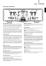
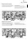
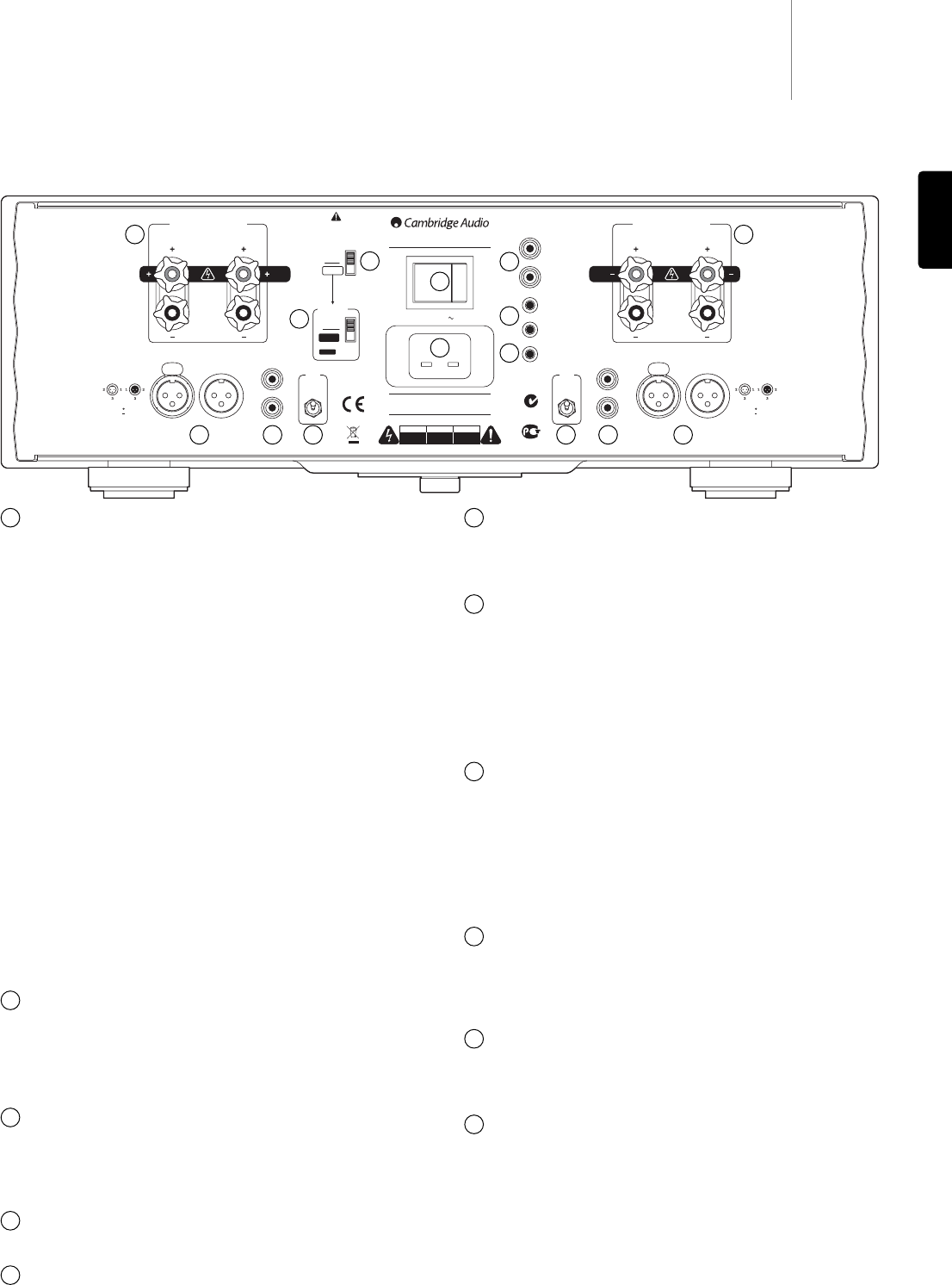
Rear panel connections
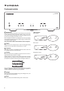
Loudspeaker terminals
For normal wiring, connect the wires from your left channel loudspeaker
to the LEFT + & - terminals, and the wires from the right channel
loudspeaker to the RIGHT + & - terminals. In each case, the red terminal
is the positive output and the black terminal is the negative output.
Other dual mono schemes are also possible if two 840Ws are used.
Refer to later sections of this manual for more information.
Use speakers with a nominal impedance of between 4-8 ohms. Care
should be taken to ensure no stray strands of wire short the
loudspeaker outputs together. Please ensure that the loudspeaker
terminals have been tightened completely to provide a good electrical
connection. It is also possible for the sound quality to be affected if the
screw terminals are loose.
Audio input types
The 840W features either unbalanced (phono/RCA) or balanced (XLR)
input connections. Either type may be used but not both at the same
time. The balanced connection is the higher quality option and can
reject noise and interference in the cable when used with other
equipment that supports this function. An XLR connector is wired Pin 1
- Ground; Pin 2 - Hot (in-phase); Pin 3 - Cold (phase-inverted).
Use the Left and Right Input Type switch (Item 4) to select the
connection type you wish to use. When using either the balanced or
unbalanced input, make sure that no cables or equipment are
connected to the unused input, as this may degrade operation. The
unused input does not need to be terminated and this should not be
done.
Balanced Audio
For connection to the balanced XLR outputs of suitable pre-amplifiers
that have this kind of output (such as our own 840E model). The pre-
amplifier used should be capable of providing at least 1V rms of output
per phase (i.e. at both of + and – terminals of the XLR, more is also
fine). Nearly all modern pre-amplifiers fulfill this requirement.
Unbalanced Audio
For connection to the normal (single ended) RCA/Phono outputs of a
suitable pre-amplifier (such as our own 840E model). The pre-amplifier
used should be capable of providing at least 1V rms of output (more is
fine). Nearly all modern pre-amplifiers fulfil this requirement.
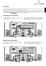
Input Type switch
Use to select a balanced or unbalanced connection type for the input.
Stereo/Mono mode switch
Switches the 840W between ‘normal’ Stereo operation (where one
840W is used for a pair of speakers) and Mono operation (where two
840W’s are used one for each speaker). Refer to later sections of this
manual for more information.
Mono mode switch
When Mono mode has been selected, switches the 840W between Bi-
Amped Mono and Bridged Mono. Refer to later sections of this manual
for more information.
Control Bus
In - Allows un-modulated commands from multi-room systems or other
components to be received by the unit.
Out - Loop out for Control Bus commands to another unit.
The 840W can also be switched between On and Standby mode by
connecting the Control Bus output of an 840E pre-amplifier to the
Control Bus input of the 840W. Refer to the ‘Power syncing’ section of
this manual for more information.
Trigger In, Out/Thru
For Custom Install use, the 840W can be turned on and off (i.e. brought
in and out of Standby mode) by the presence of 5-12V DC at the Trigger
input. A trigger input will also produce an internally generated 12V DC
trigger output at the Output/Thru connection. Turning the 840W on from
the front panel also produces a 12V DC trigger output at the
Output/Thru connection. This can be used to turn on/Standby other
connected power amplifiers or other equipment if desired. Refer to the
‘Power syncing’ section of this manual for more information.
IR (Infra-Red) Emitter In
Allows modulated IR commands from multi-room systems or IR repeater
systems to be received by the unit. Commands received here are not
looped out of the Control Bus. Refer to the ‘Custom installation’ section
for more information.
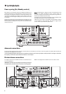
AC power socket
Once you have completed all connections to the unit, plug the AC power
cable into an appropriate mains socket then switch on. Your unit is now
ready for use.
Power On/Off
Switches the unit on and off. If the 840W is not going to be used for long
periods of time it should be turned off using this switch.
1
1
6
5
2 3 4
1
4 3 2
10
11
9
8
7
2
3
4
5
6
7
8
9
10
11