


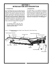
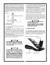
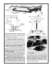
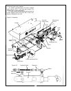
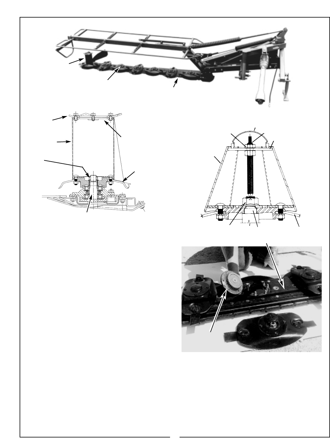
Figure 4-5
Blade Disc Cap Covering
Retaining Nut
Standard Crop
Divider
Cutter Bar
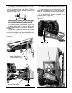
The blade disc assembly is now ready to be
removed from the cutter bar. If required, a steady
prying force on either side of the cutter bar, spaced
180° apart, can aid in removing the blade disc
assembly from the spindle shaft.
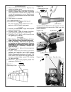
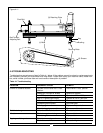
C. Remove the six (6) M10 nuts connecting the
spindle assembly to the cutter bar. (Figure 4-8)
D. Lightly tap a screwdriver into the two slotted
notches cast into each spindle housing, positioned
180° apart. Simultaneously and with equal force,
press downward on the two screwdrivers. When the
sealant attaching the spindle housing to the cutter
bar has been broken, remove the entire spindle
assembly from the cutter bar taking special care
to keep dirt and debris out of the cutter bar.
E. Prior to reassembling the spindle assembly
onto the cutter bar (see your Bush Hog Repair Parts
Catalog for the spindle assembly part number), thor-
oughly clean the top face of the cutter bar casing
where the spindle was originally located of all
old sealant, oil and dirt.
F. Draw a bead of oil resistant gasket sealant
(Dow Corning 735 sealant recommended by
manufacturer) around the perimeter of the spin-
dle housing opening in the cutter bar casing.
G. Position the spindle assembly over the six
(6) M10 bolts (ensuring that blade disc will
assemble at 90° to the adjacent assembly) and
join the spindle assembly to the cutter bar using
the six (6) M10 nuts removed in Step C. Apply
Loctite 242 thread sealant to the threads of the
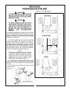
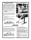
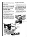
Figure 4-7 Optional Crop Divider
Cutter
Cap
Hub Cap
Threaded Rod
Cap
Jam Nut
Crop
Divider
Retaining Nut
Output Shaft
Blade Disc
Assembly
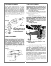
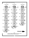
Crop
Divider
Retaining
Nut
Output Shaft
Blade Disc
Assembly
six (6) M10 bolts and torque the nuts to a value
of 62.5 - 73 ft./lbs.
H. Install blade disc assembly onto the same
gear assembly from which it was removed, making
sure the blades of the disc assembly being
installed are exactly 90° apart from both adjacent
blade disc assemblies to ensure proper timing.
Tighten the retaining nut to 200 ft./lbs. The outer
gear housing assembly has the crop divider assem-
bled to the blade disc assembly. The cap for the
crop divider must be installed.
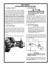
Figure 4-8 Cutter Bar
Spindle
Assembly
15
(Curtain Removed To Show Details Only)
Figure 4-6 Standard Crop Divider