


28B-SST Amplifier
4
Power Control
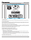
(refer to figure 1 on page 2)
7. Master circuit - breaker.
The 28B-SST amplifier uses a magnetic-trip circuit breaker to protect the amplifier.
This switch should be ‘OFF’ during installation. When switched ‘OFF’
All A/C power is removed from the amplifier, including standby power.
The circuit breaker is not the power switch and should be switched to and left ‘ON’ after the installation is complete.
Use the 28B-sst front panel power switch or an external control voltage to Power-up or Power-down the amplifier.
Should the breaker trip, lower or remove the amplifier input signal (also see section 9 below). Switch the breaker to the
‘ON’ position. Then power the unit up normally.
The circuit breaker must be ‘ON’ at all times for the 28B-SST amplifier to operate.
8. AC power input.
On the rear panel is provided a high current plug for the power cord receptacle. Check that the voltage rating on the label
(item 12 in figure 1, page 2) conforms with your locality. With the circuit breaker ‘OFF’ insert the power cord into the 28B-
SST amplifier, then plug the other end to an appropriate A/C power outlet. Switch the circuit breaker to on and observe
the LED labeled "Line Voltage Status Indicator".
9. LINE VOLTAGE STATUS INDICATOR
This LED will be on anytime the amplifier is plugged into a source of electrical power and the circuit breaker (#8) is ON.
The amplifier cannot turn on unless the LED will is green.
Should the amplifier not power on, and the LED is flashing, remove the power cord from the rear of the amplifier and wait
a few seconds then plug the power cord back in.
Should the LED be red, a condition exists preventing the amplifier from powering up.
Reasons: the applied electrical power is outside the operating range, 120v unit connected to 230v, Check the electrical
ratings label on the rear panel to see if the voltage is correct for your location. Otherwise consult your dealer or call the
factory.
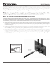
10 & 11: External control voltage power up ( Local/External switch & Interface Connector)
● To power-up the SST amplifier using an external control voltage:
1) The circuit breaker (#8) and front panel power switch (#13) must both be ON
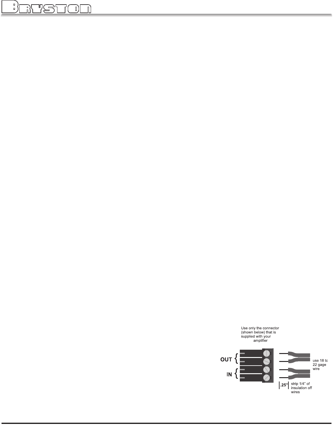
2) Supply a 4v to 12v A/C or DC control voltage to the ‘IN’ terminals of connector ( #11 )
3) Use paired wire of 22 to 18 gage sufficient in length between the source device and the SST amplifier.
4) Set slide switch (item 11 in figure 1, page 2) to “External”. The amplifier will now power-up only when the control
voltage is present (on) and the front panel push-button power switch is ON (depressed). Immediately following
power up, the control voltage will appear at the ’OUT’ terminals of the interface connector (item 10 on figure 1,
page 2, also see below) for the control of other equipment. The removal of the control voltage (0v), or releasing
the front panel power switch, causes the amplifier to turn ‘off’ and the control voltage at the ‘OUT’ terminals is
interrupted.
● In the "Local” setting:
The 28B-SST amplifier will ignore the control voltage, and power up only by using the front panel ‘28B-
SST POWER’ switch, or as in section 3 above. If a control voltage is pres-
ent at the ‘IN’ terminals it will still be available at the ‘OUT’ terminals after
the power-up sequence.
Note:
The ‘OUT’ terminals are connected to the ‘IN’ terminals once the 28B-SST amplifier has pow-
ered-up. The control current is determined by the source equipment. The carrying current of
the ‘OUT’ relay is 2 amps. The 28B-SST control circuitry itself draws less than 2 mA from the
control current when operating.
28BSST