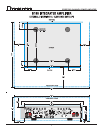
B100 TWO CHANNEL POWER AMPLIFIER
3
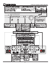
ANALOG4Aux2 / DIGITAL4Select:
In B100-DA models: when this LED is illuminated green concurrently with either D1, D2, D3
or D4 LEDs, it indicates that the digital inputs d1 (SPDIF), d2 (SPDIF), d3 (TOSLINK) or d4
(TOSLINK) have been selected.
In B100 & B100-P models: when illuminated green this LED indicates that the line level ana-
log audio input AUX-2 has been selected.
AUX1, CD, TUNER, TV/SAT VIDEO & RECORD:
One of these input source LEDs will light green to Indicate the active input. In digital mode
these LEDs will light RED if the bit stream is either absent or unacceptable.
BALANCE When the left/right signal balance is being shifted one of these LEDs will light to indicate
which channel is being attenuated. Balance can be adjusted in 1dB increments to up to
-6dB in either direction. Stepping past -6dB in either direction will mute that channel fully
and the LED for that channel will turn red.
When both LEDs are on (red), PASS THROUGH mode is indicated. (See “Pass Through
Mode” on page 4)
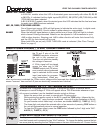
REMOTE POWER CONTROL ~ 12 VOLT TRIGGER CONNECTOR:
Two trigger outputs are provided. A 12Vdc signal is placed across
the T1 and C pins of the 12V
TRIGGERS connector whenever
the unit is fully powered up.
Then the unit goes into standby
this voltage is removed.
A 12Vdc signal will be placed
across the other pair of 12V
TRIGGER output pins (T2) when-
ever a certain user programmed
input is selected as the source
input (see below for program-
ming instructions). When any
other input source is selected the 12Vdc control voltage will be removed from these pins. Please note that C
means “common” here and both C pins are electrically connected and identical.
PROGRAMMING the “T2” 12v TRIGGER OUTPUT:
By default the T2 triggered output is inactive. To program this output to become active ,
whereupon a control voltage of 12Vdc will appear across T2 & C terminals whenever a spe-
cific source is selected, use the handheld remote control as follows:
• Select the source that you want to coincide with T2 going active.
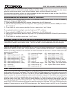
• While pointing the remote control at the B100, press the CODE button, followed by the
three digit code “247” using the keys numbered 1 through 0 in the illustration at the left.
On your remote control these keys, or buttons, are labeled AUX/PH (2), TUNER (4), D1 (7).
• The three digit code should be entered within a few seconds of pressing CODE button or
the unit will automatically return to normal operation.
• To clear the T2 trigger output, press the CODE button followed by the 3 digit code “248”:
AUX/PH (2), TUNER (4), D2 (8).
HAND-HELD INFRA-RED REMOTE CONTROL:
The Bryston model B100 comes standard with a full function hand-held remote control unit. The
hand held remote unit is powered by two “AAA” batteries. To change the battery remove the bot-
tom cover plate by removing the four Philips screws on the rear of the remote unit. Ensure that the


