


875Z - EIGHT CHANNEL POWER AMPLIFIER
2
2
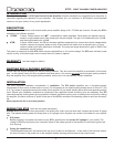
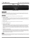
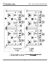
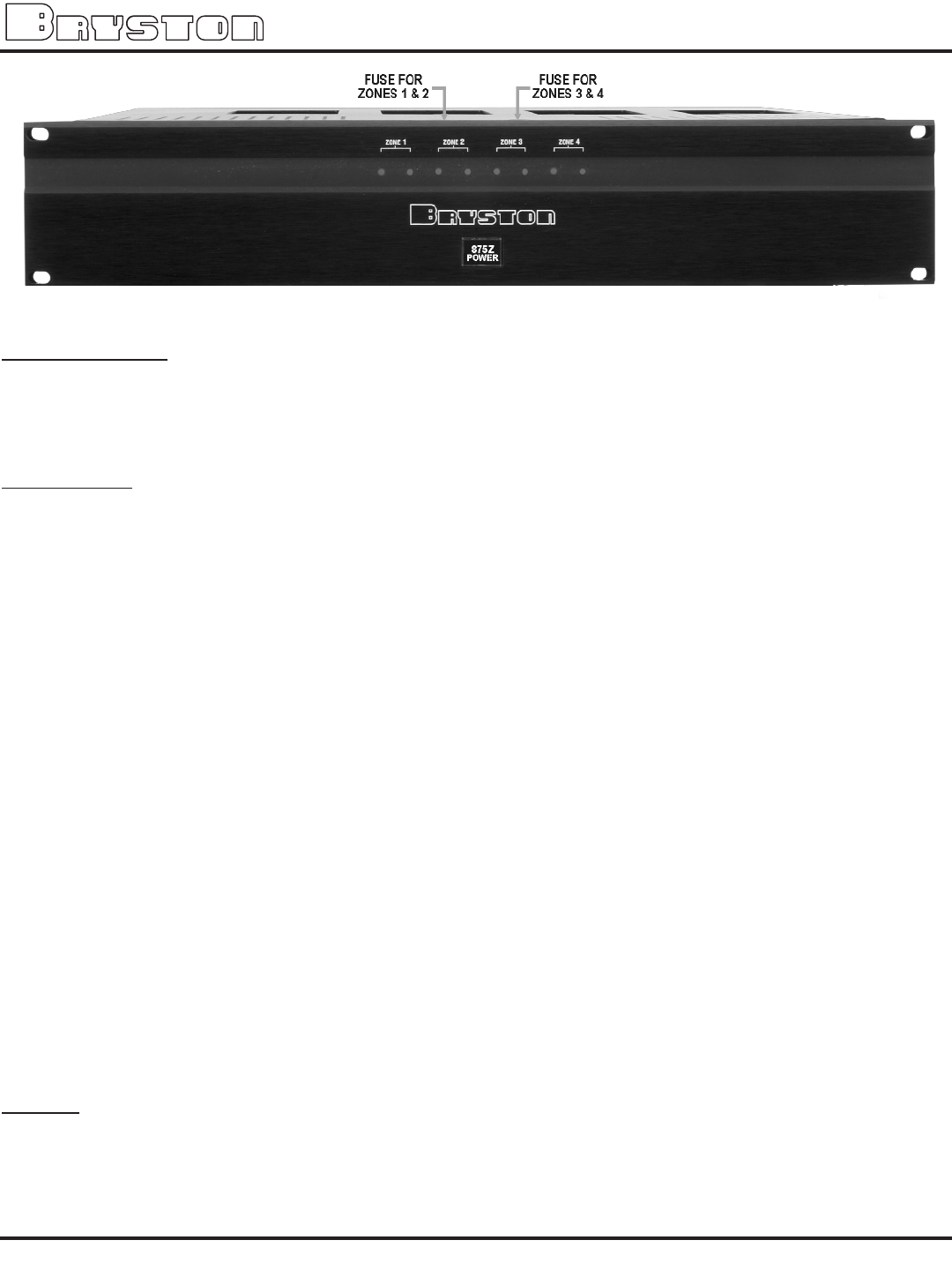
FRONT PANEL of 875Z-Blk
FRONT PANEL
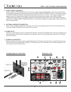
POWER switch
The front panel label '875Z POWER’ is a switch used to apply or remove A/C line power to the 875 soft start circuitry.
Push the switch and the 875 will initiate the start up sequence. The switch cap remains indented when circuits are on.
Push the switch again the 875 will initiate the power off sequence.
LED Indicators:
Each 875 channel has a single multi-colour LED indicator to monitor the following conditions:
P
Unlit LED: no power
The 875 channel LED, when unlit, indicates no A/C mains power is present at the channel. If all channel LED indica
tors are unlit the 875 probably needs only to be powered on. A group of 4 LEDs not lighting possibly indicates a
blown group fuse. When checking fuses, unplug the power cord. Use only the specified fuses for your operating volt
age. See FUSES section below.
P
Red LED: muted
Each channel normally mutes momentarily during power up and power down sequences.
P
Green LED: operating normally
P
Flashing Red LED: Clipping
Clipping occurs when the channel output level no longer can follow the level increase at the input (Over driven input
condition). When a 875 channel is driven into clipping the channel led will change from green to red then back to
green when the level is reduced ( Flashing Red ). Momentary clipping can be tolerated, however it indicates that
maximum un-distorted power has been surpassed and potential speaker damage may result if over load conditions
persist. Any amplifier that is constantly operated into clipping indicates a more powerful amplifier is needed for that
application.
P
Orange LED: Thermal Shutdown
The 875 channel has thermal shutdown circuitry to prevent damage due to over heating. Should thermal shutdown
occur, the both stereo channels will mute, and the channel leds will turn orange indicating this condition. When the
channels have cooled to a safe operating condition the channels will return to normal operation. Persistent Thermal
shutdown indicates steps need to be taken to increase airflow across the channels heat sink.
(Also see installation section on ventilation ).
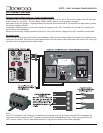
FUSES
There are two fuse holders located at the front edge of the top panel. When checking fuses, power down the unit and dis-
connect the power cord. Use only the specified fuses as indicated on the label located between the two fuse holders on
the top panel. See photo at top of page.