


7B SST Series Amplifier
5
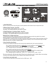
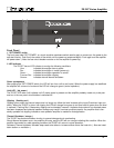
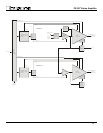
Power Control
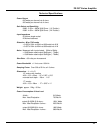
1. Master circuit - breaker.
The 7B SST amplifier uses a magnetic-trip circuit breaker (1) to protect the amplifier.
This switch should be ‘OFF’ during installation. When switched ‘OFF’
all A/C power is removed from the amplifier, including standby power.
The circuit breaker is not the power switch and should be switched to and left ‘ON’ after
the installation is complete. Use the “SST POWER” switch or an external control voltage
to Power-up or Power-down the amplifier.
Should the breaker trip, lower or remove the amplifier input signal. Switch the breaker to
the ‘ON’ position. Then power the unit up normally.
The circuit breaker must be ‘ON’ at all times for the 7B SST amplifier to operate.
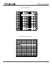
2. AC power input.
On the rear panel is provided a high current plug for the power cord receptacle. Check that the voltage rating on the label
conforms with your locality. With the circuit breaker ‘OFF’ insert the power cord into the 7B SST amplifier, then plug the
other end to an appropriate A/C power outlet.
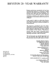
3. Power-Up ( Local / Auto switch. )
A. In “Local” position either the front panel ‘SST POWER” switch or an
external voltage controls the power-up of the 7B SST amplifier.
B. “Auto” is used when the 7B SST amplifier is powered from a switched power outlet.
The ‘SST POWER’ switch and / or control voltage will function normally
after the initial power up.
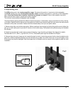
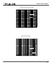
4. External control voltage power up ( Local / external switch.)
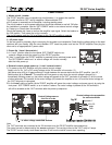
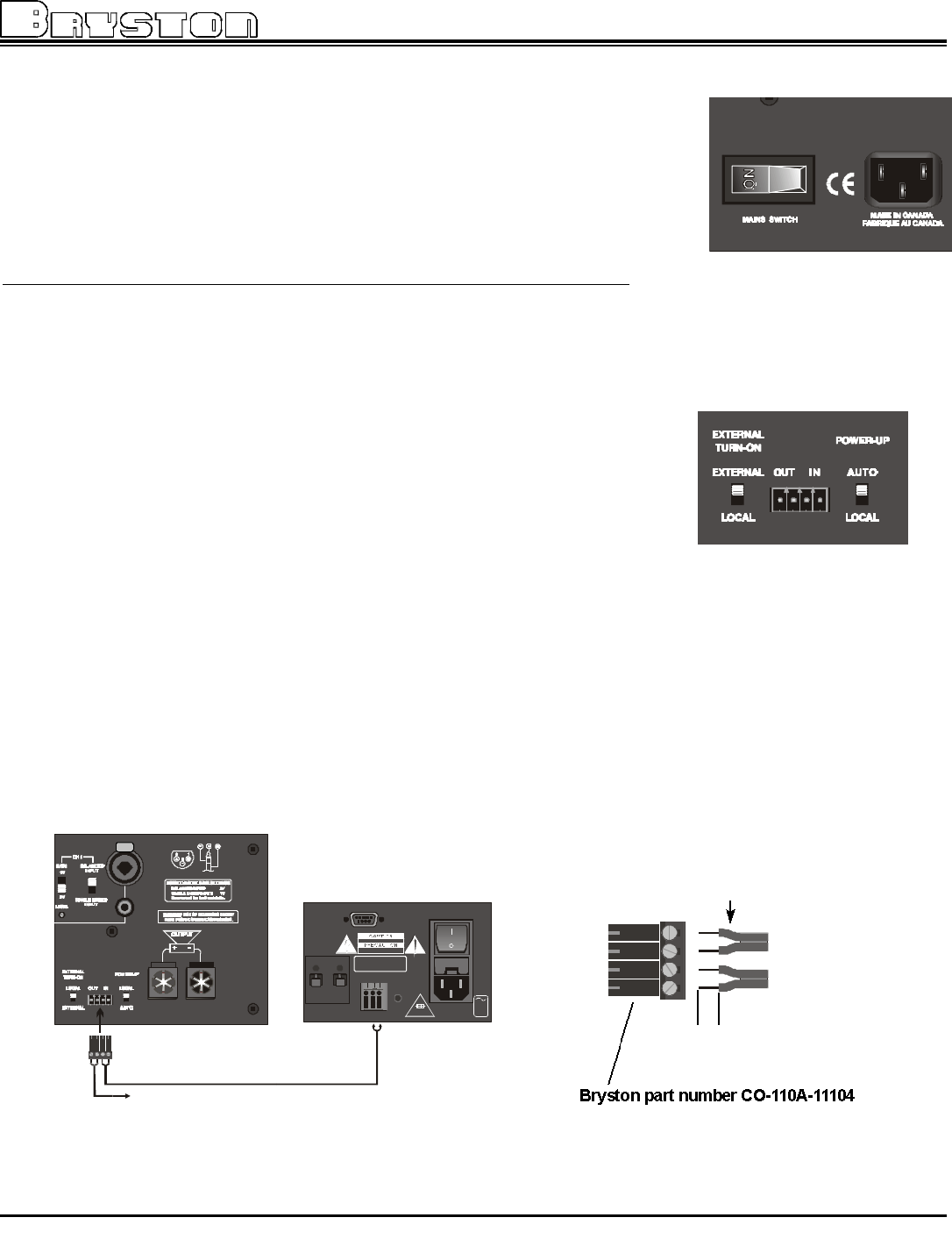
A. To power-up the SST amplifier using an external control voltage,
Supply a 4v to 12v A/C or DC control voltage to the ‘IN’ terminals of connector ( 5 ).
Use paired wire of 22 to 18 gage sufficient in length between the source device and the SST amplifier. (see ‘W’ )
Select switch (4) to “External”. The amplifier will now power-up only when the control voltage is present (on).
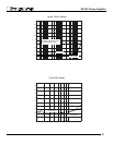
Immediately following power up, the control voltage will appear at the ’OUT’ terminals of connector (5) for the control
of other equipment.The removal of the control voltage (0v) causes the amplifier to turn ‘off’ and the control voltage at
the ‘OUT’ terminals is interrupted.
B. In the“Local” setting of switch (4) the 7B SST amplifier will ignore the control voltage, and power up only by using the
front panel ‘SST POWER’ switch, or as in section 3 above. If a control voltage is present at the ‘IN’ terminals it
will still be available at the ‘OUT’ terminals after the power-up sequence.
OPT2OPT1
ON/OFFMUTE C
AUX. IR
F2A 250V 20W
60Hz
120V
RS-232
EXP.
NE PAS OUVRIR
RISK OF ELECTRIC SHOCK - DO NOT OPEN
RISQUE DE CHOC ELECTRIQUE
SERIAL NUMBER
12V TRIG. OUT
SP1-
PUSH
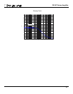
1/4”
strip
Control voltage wire preparation
for screw terminals
18 to 22
gage
wire
separate 1”
Control Voltage source
4 to 12v ac or dc
Note:
The ‘OUT’ terminals are connected to the ‘IN’ terminals once the 7B SST amplifier has powered-up.
The control current is determined by the source equipment. The carrying current of the ‘OUT’ relay is 2 amps.
The 7B SST control circuitry itself draws less than 2 mA from the control current when operating.
to other voltage controlled devices
fig W
4 3
1
2