


3Bsst & 4Bsst POWER AMPLIFIERS
4
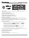
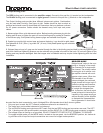
6. Output binding posts.
The RED binding post is connected to the amplifier output. Connect to this post the (+) terminal on the loudspeaker.
The BLACK binding post is connected to signal ground. Connect to this post the (-) terminal on the loudspeaker.
The Output binding posts provide three different interconnect options. Combinations
may be used when bi-wiring. See figure at right. Cables should be kept as short as
practical and should never be terminated with connectors that may become confused
for AC power connectors. Cables should be dressed away from input and power
cables.
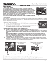
1. Banana plugs offer a quick disconnect option. Before inserting a banana plug into the
binding post be sure to tighten the post nut to avoid rattling and to provide full insertion
of the banana plug. Gold plated locking banana plugs are available from Bryston.
2. Spade lugs provide high contact area and secure fastening. Lugs should be gold plated.
Post diameter is 5/16’ ( 8mm ), lug width 5/8” (16 mm). Gold plated spade lugs are available
from Bryston.
3. Stripped bare wire up to 3 gage can be inserted through the hole in the binding post and held in place by tightening the
post knob. Additional tightening pressure can be achieved using a coin in the slots of the knob. Do not over tighten or the
binding post may become damaged. Note that copper wire is malleable and may require further tightening after the initial
installation.
5/8”
5/16”
2
3
1
coin
OPERATION
BRIDGED MODE
Bridged mode” refers to the com-
bining or “bridging” of two ampli-
er channels into a single ampli-
er channel. The primary reason
for doing this is to achieve a sin-
gle amplier channel with much
greater output power. When two
3B channels or two 4B chan-
nels are bridged, the combined
single channel will output up to 2
times the voltage and therefore,
theoretically, 4 times the power
of a single non-bridged chan-
nel. In practice, the actual output
power achieved is limited by the
capability of the power supply as
well as the ability of the amplier
to dissipate the increased heat
that is generated. It should also
be noted that the load connected to a pair of bridged 3B or 4B channels should be 8 ohms or greater.
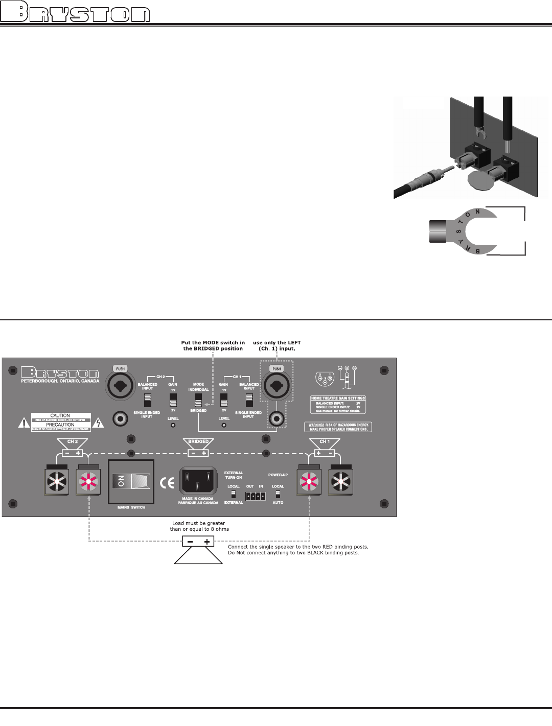
• Only one input is used: the LEFT channel (sometimes referred to as channel #1).
• The single input can be either balanced or un-balanced.
• The two BLACK binding post outputs are NOT used. Only the two RED binding post connectors are used. The LEFT
(Ch. 1) binding post is the positive polarity connector and the RIGHT (Ch. 2) RED binding post connector is negative.
• The bridged output is oating or un-grounded. DO NOT CONNECT EITHER OUTPUT TERMINAL TO GROUND.
• To engage bridged mode, put the MODE switch, located on the rear panel, into the BRIDGED position, but. before do-
ing so make sure all input and output connections are correct for bridged mode operation.
Figure 2