


I
nstallation Instructions (cont.)
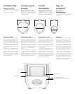
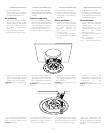
2. Cut the installation hole.
3. Run the wire from the amplifier
location to the cutout. Allow for an
extra foot of wire at the cutout.
All Installations
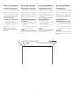
1. Strip
1
/2-inch (13mm) of insulation
from the wire, and twist the wire
s
trands together. The VSi speaker
jack will accept either bare wire up
to 12-gauge, or single banana
plugs.
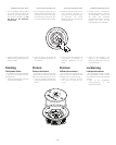
2. Connect the wire to the speaker.
3
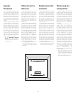
. Slide the speaker into the cutout.
– 11 –
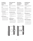
4. Tighten the 4 Phillips mounting
screws. The mounting arms will
pivot into position and clamp the
speaker to the mounting surface.
Imp
or
tant:
Do not overtighten the
screws.
If you wish to paint your speakers or
g
rilles, it should be done prior to instal-
lation of the g
rille. Please see the
P
ainting
instruc
tions.
I
nstrucciones de Instalación (cont.)
2. Corte el agujero para la instalación.
3. Tienda el cable desde el amplificador
hasta el final. Corte a 30 cm más de lo
necesario.
Todas las instalaciones
1. Pele 13 mm del aislante del cable y
retuerza el extremo para agrupar los
h
ilos. El conector del altavoz VSi
acepta tanto alambre de calibre 12
como clavijas sencillas tipo banana.
2. Conecte el cable al altavoz.
3. Introduzca el altavoz en el agujero.
4. Apriete los tornillos de estrella o cruz
de montaje. Los brazos de montaje
girarán hasta su posición y manten-
drán el altavoz sujeto a la super
ficie
del montaje
.
Importante:
no apriete demasiado los
tornillos.
Si quiere pintar los altavoces o las
r
ejillas deberá hacerlo antes de la
instalación de la r
ejilla. Consulte las
instrucciones para pintar
los.
I
nstructions d’installation (suite)
2. Découpez l’orifice d’installation.
3. Amenez le câble de l’ampli à l’ori-
fice que vous venez de découper,
en prévoyant 30 cm de câble sup-
plémentaire.
Toutes installations
1. Dénudez 13 mm de câble, et tor-
s
adez les fils souples ensemble.
La fiche de l’enceinte VSi accepte
les câbles dénudés d’un
diamètre maximum de
calibre 12, ou les fiches
b
ananes simples.
2. Connectez le câble à l’enceinte.
3. Introduisez l’enceinte dans l’orifice
découpé.
4. Revissez les vis de fixation. Les sup-
ports de fixation pivotent en posi-
tion et fixent l’enceinte sur la sur-
face de fixation.
Imp
or
tant :
Ne resserrez pas les vis
excessivement.
Si vous voulez peindre les enceintes
ou les g
rilles, faites-le avant l’installa-
tion des g
rilles. Veuillez consulter les
instruc
tions de peinture qui suivent.
I
nstallationsanweisungen (Forts.)
2. Das Montageloch schneiden.
3. Das Kabel vom Verstärker zum
eben erzeugten Ausschnitt verlegen.
An der Ausschnittstelle etwa 30 cm
extra Kabellänge vorsehen.
Alle Installationen
1. 13 mm Isolierung vom Kabel ent-
m
anteln, und die Drahtlitzen
zusammendrehen. Der VSi-
Lautsprecheranschluss nimmt
entweder blanken Draht bis zu
AWG 12 oder einfache
G
abelschuhstecker auf.
2. Das Kabel an den Lautsprecher
anschließen.
3. Den Lautsprecher in den
Ausschnitt schieben.
4
. Die Kreuzschlitz-Befestigungs-
schrauben festziehen. Die
Montagearme schwenken in die
Einbaustellung und klemmen den
Lautsprecher an der
Montagefläche f
est.
Wichtig:
Die Schrauben nicht zu fest
anziehen.
Wenn die Lautsprecher oder
Zier
gitter lackiert werden sollen, muss
dies v
or der Installation des Ziergitters
geschehen (siehe An
weisungen zum
Lack
ieren).