


AM251174_03_V.pdf October 22, 2001 9
POWER
12VAC IN
~
1.0A
SYSTEM
CONTROL
1
2
AM
LOOP
ANTENNA
AUX VIDEO SOUND
R
INPUT
PLAYREC
L
FIXED TAPE
B
Z
T
G642
950 D S
BOSE Corporation
U
L
®
LISTED 917D
AUDIO
EQUIPMENT
MANUFACTURED:
geprüdfte
Sicherheit
93
TÜV Rheinland
BOSE CORPORATION, FRAMINGHAM, MA 01701-9168 MADE IN USA
®
LIFESTYLE MODEL 5 MUSIC CENTER
®
OUTPUT
BA
R
L
SPEAKERS
RIGHT
OUTPUTS
TO
CUBE
SPEAKERS
LEFT
AUDIO
INPUT
OFF
POWER
ON
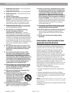
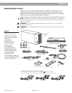
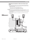
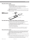
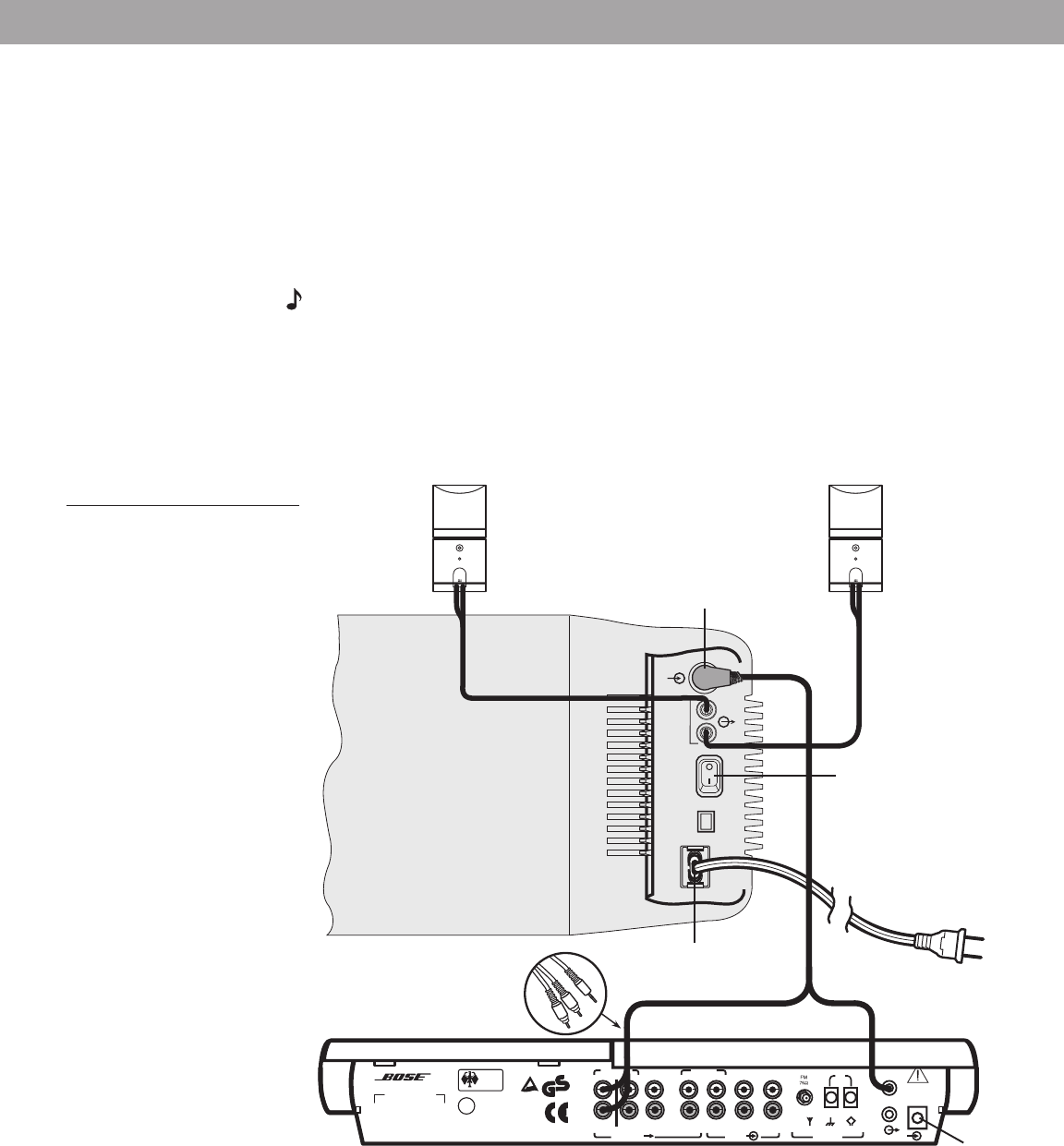
Connecting the Acoustimass
®
module to the Lifestyle
®
music
center
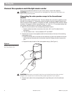
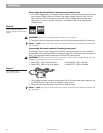
Connect the Acoustimass module to the music center with the audio input cable (Figure 5).
1. Insert the three connectors at one end of the audio input cable into the jacks on the rear
panel of the music center:
• Black connector into the SYSTEM CONTROL 1 jack
• Red connector into the R (right) SPEAKERS A OUTPUT jack
• White connector into the L (left) SPEAKERS A OUTPUT jack
Note:
Be sure the connectors are fully inserted into each of the jacks. If the black connector
is not inserted fully into the SYSTEM CONTROL jack, you will hear no sound.
2. Insert the single right-angle multi-pin connector on the other end of the audio input cable
into the AUDIO INPUT jack on the Acoustimass module. Align the connector at the angle
shown in Figure 5.
3. Extend the audio input cable as much as possible, since it includes an antenna for the
remote control.
Figure 5
Music center and speaker
connections
AC power
jack
Black connector
into SYSTEM
CONTROL 1
Right-angle
connector
into AUDIO
INPUT
Audio
input
cable
AC power
jack
Left
speaker
Right
speaker
Red and white connectors
into matching
SPEAKERS A OUTPUTs
Setting Up
Power switch