


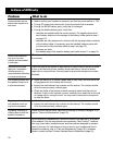
15
Installed connector
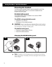
An optional installed connector is available for pilots who want to hardwire the
DC power, incoming audio, and outgoing microphone functions permanently
into their plane. The panel mount receptacle comes wired with a 6 foot harness
to simplify the installation process. To order this connector, contact the Bose
Aviation Headset Service Department (page 23).
The Bose
Aviation Headset Series II uses a self-latching, precision designed
quick connector. A mechanical keying system ensures greater ease in mating.
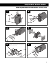
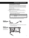
Installing the wire harness
Note:
This installation must be done by mechanics qualified to perform this type
of avionics installation for the aircraft in which the installed connector will be used.
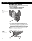
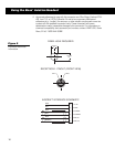
A .5 in. x .56 in. (1.27 cm x 1.42 cm) cutout is required to mount the connector as
shown in Figure 9. There are 6 wires to connect: 2 for microphone, 2 for audio, 1
for power, and 1 for ground. The audio and microphone wires should be con-
nected to the back of the existing microphone and phone jacks. This leaves the
existing jacks intact for use with conventional headsets and is usually the fastest
installation method.
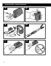
The pinout for the optional installed connector is as follows:
Pin Wire Description
1 Red Headset power (7-32 Volts DC). Use a .5 amp fuse or circuit
breaker.
2 Black System ground. Connect to the existing audio ground.
3 White Phone communication-left.
4 Black Phone communication-right.
5 White Mic/Hi-audio. Connect to the existing portion of the mic jack
that corresponds to the ring position of a headset micro-
phone plug. Do not connect to the tip (PTT) segment.
6 White/Blue Mic/Lo-ground. Connect to the existing portion of the mic
jack that corresponds to the barrel position of a headset
microphone plug.
Notes:
1. If used with a stereo intercom, connect the left and right channels to their
respective positions. For mono operation, connect Pins 3 & 4 together to the
tip portion of the existing phone jack.
2. Do not bend or use excessive force on the installed connector. Doing so may
damage or break the internal solder joints.
3. If the boom mic works on radio transmit but not through the intercom, check
Pin 6. It is probably miswired to the PTT segment of the mic jack.
4. The wire connecting Pins 3 & 4 and 5 & 6 are shielded, twisted pair with a
shield termination exiting with a black wire for each pair. Connect shields to
existing audio wiring shields, or audio ground if the existing wiring is not
shielded.
Using the Bose
®
Aviation Headset