


DS240/DS241 Installation Instructions © 2004 Bosch P/N: 22066P Page 7
To check the reference voltage, remove the receiver's access door
and measure the reference voltage, using the supplied test cable, or
measure the voltage at the DIS240 Remote Indicator Plate (if used).
If the voltage is less than 3.8 VDC, remove the cover and perform a
fine tune alignment including use of the Set-up switch. If above 4.2
VDC, press the Set-up button. Calibration is not necessary if the
voltage is between 3.8 VDC and 4.2 VDC.
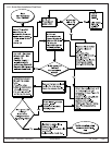
8.4 Power Outage
When power is removed, then reapplied to the receiver (such as in a
power outage or alarm reset), the original reference voltage
information is lost.
If the cover is on at the time of power-up, the receiver will automatically
restart the internal set-up process (to get a new reference voltage)
when power is applied. If the cover is off, the Set-up button will have to
be pressed after the cover is reattached.
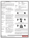
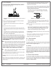
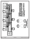
8.5 Remote Indicator Plate Connector
Momentarily connecting the orange and black leads of the connector
(see
Figure 16
) will produce a test alarm. For a remote test, install a
momentary switch between the orange and black wires.
ORANGE - Remote Alarm Test
BLUE - Analog ref. voltage out
BLACK - Common (-)
RED - Red LED indicator
YELLOW - Yellow LED indicator
GREEN - Green LED indicator
Figure 16 - Remote Indicator Plate Connector
The black and blue wires may be connected to an analog meter for
reference voltage measurements. The red, yellow, and green wires
may be connected to remote LEDs.
Each wire is current limited to a maximum of 10.0 mA DC.
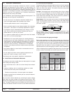
8.6 Smoke Density/Obscuration Information
The total obscuration of the infrared beam is dependent upon the
density and width of the smoke cloud along the beam path. As the
width of the smoke cloud increases along the beam path, less dense
smoke will be needed for an equal obscuration of the beam path. In
practice, the smoke cloud is assumed to be the entire distance of the
beam path; therefore, the total obscuration required for alarm should
be selected by setting the Sensitivity Pot Setting as recommended in
Section 7.2 Sensitivity Adjustment
on page 5.
Since the total obscuration of the beam by smoke increases with
distance between the units (because more smoke will be within the
beam path), the detector can be made less sensitive as the distance
increases. Additionally, the sensitivity of the detector should be made
less at greater distances because obscuration by other contaminants
such as dust increases. The sensitivity should be set to respond to
the proper smoke obscuration and also to reduce the chance of a
false activation.
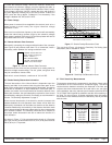
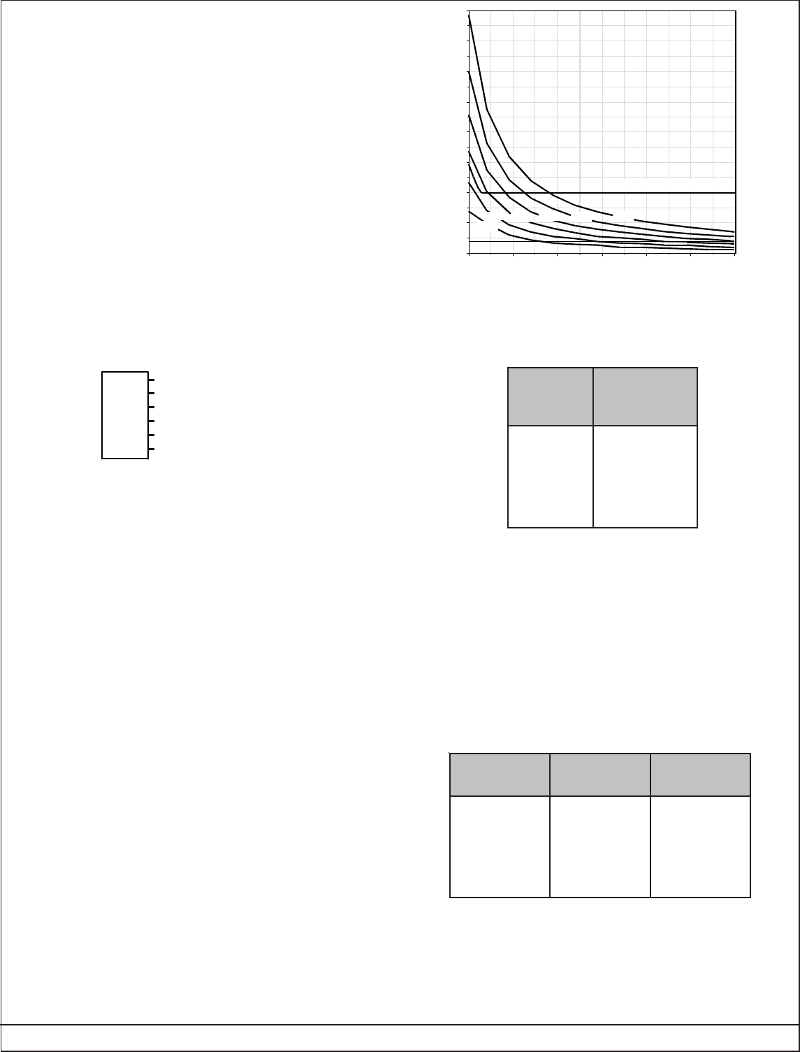
As shown in
Figure 17
, if the expected smoke density is 0.5 percent
per ft (per 30 cm), the obscuration at 50 ft (15 m) is 20 percent and at
250 ft (95 m) it is 73 percent.
Figure 17 - Smoke Density/Obscuration Chart
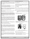
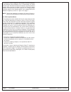
The next chart (
Figure 18
) shows the Sensitivity Pot Setting (total
obscuration) that is needed for alarm.
Figure 18 - Sensitivity Pot/Obscuration Chart
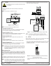
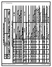
8.7 Field Sensitivity Measurements
The detectors automatically compensate for the effects of dust or dirt
accumulation on the covers and for component aging. The NFPA
requires that the detector's sensitivity be measured in the field, and
requires that these measurements be made within one year after
initial installation and every alternate year thereafter (reference NFPA
72). A TK240 Test Kit should be ordered to test the unit’s sensitivity in
the field. The chart (
Figure 19
) below represents alarm information
for the filters in the TK240 as well as the Sensitivity Test Kit provided
with the units.
Figure 19 - Sensitivity/Response Chart
ytivitisneS
toP
gnitteS
latoT
noitarucsbO
mralAta
2
3ro0
4
5
6ro1
7
%02
%03
%04
%05
%06
%07
ytivitisneS
gnitteS
TONtsuM
mralA
TSUM
mralA
2
3ro0
4
5
6ro1
7
)retlifon(%0
)retlifon(%0
retlif%02
retlif%02
retlif%04
retlif%04
retlif%04
retlif%06
retlif%06
retlif%08
retlif%08
retlif%08
330 (100m)280 (85m)230 (70m)
180 (56m)
130 (40m)80 (24m)
30 (9m)
0.0
0.5
1.0
1.5
2.0
2.5
3.0
3.5
4.0
UL Minimum Sensitivity
UL Maximum Sensitivity
20%
30% 40% 50%
Distance Between Transmitter and Receiver
70%60%