Operation
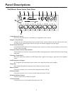
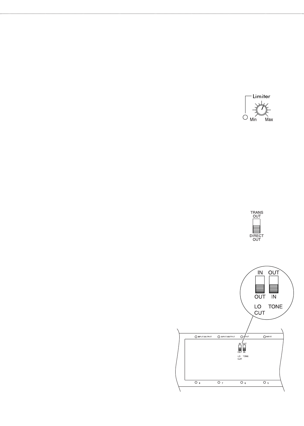
Output Limiter
The Output Limiter control sets the threshold at which the unit hard
limits the output signal. Once the Limiter's threshold is exceeded, the
output signal is prevented from increasing any further.With the control
set to the Min position (fully counterclockwise), the Limiter will pro-
vide almost no limiting and is essentially turned off. It will only engage
when very large output levels are produced.As the control is turned
clockwise, more limiter function will be allowed and the output level
necessary to engage the Limiter decreases.
Typically, the Limiter is set to prevent clipping caused by overdriving the
amplifier beyond its maximum output level.This setting is established by
using both the Output Level Meter and the Limiter LED.
First, adjust the amplifier’s output level until the Output Level Meter
registers in the amber region.Then, adjust the Output Limiter control
until the Limiter LED illuminates intermittently. The LED associated
with the Limiter illuminates when the Limiter is engaged. If the output
level of the amplifier exceeds this point, then the Limiter will engage,
thereby keeping the Output Level Meter in the amber region. The
Limiter can also be set to restrict the amplifier's output level to a
desired level below the amplifier's maximum level to provide a means
of limiting the system's volume level. In this case, the amplifier is driven
to the desired output level and then the Limiter control is adjusted so
that it begins to engage. In general,input and master controls should be
set so that the Limiter engages as little as possible.
Rear Panel Controls
Load Selector Switch
A large slide switch next to the amplifier’s output barrier strip deter-
mines transformer-coupled or direct output operation.The setting of
this switch controls which amplifier output terminals are active and
what type of filter shape will be used for the bass control. See the
Connections section for more information about the load selector
switch.
Other Controls (Located In Module Bay 6)
Tone Control Bypass Switch
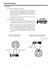
A slide switch that can bypass the effects of the Bass
and Treble controls is located on the back plane of
module bay 6. It is sometimes desirable to bypass
the tone controls when other forms of system
equalization are used.A screwdriver can be used to
set the switch. The switch must be set before a
module is installed in this bay.
Low-Cut Switch
The Power Vector Amplifier provides a low-cut filter
that rolls off frequencies below 125 Hz. The slide
switch for this function is located on the back plane
of module bay 6. A screwdriver can be used to set
the switch.The switch must be set before a module
is installed in this bay.
9


