


Panel Descriptions
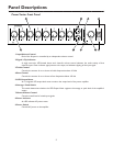
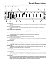
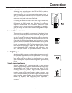
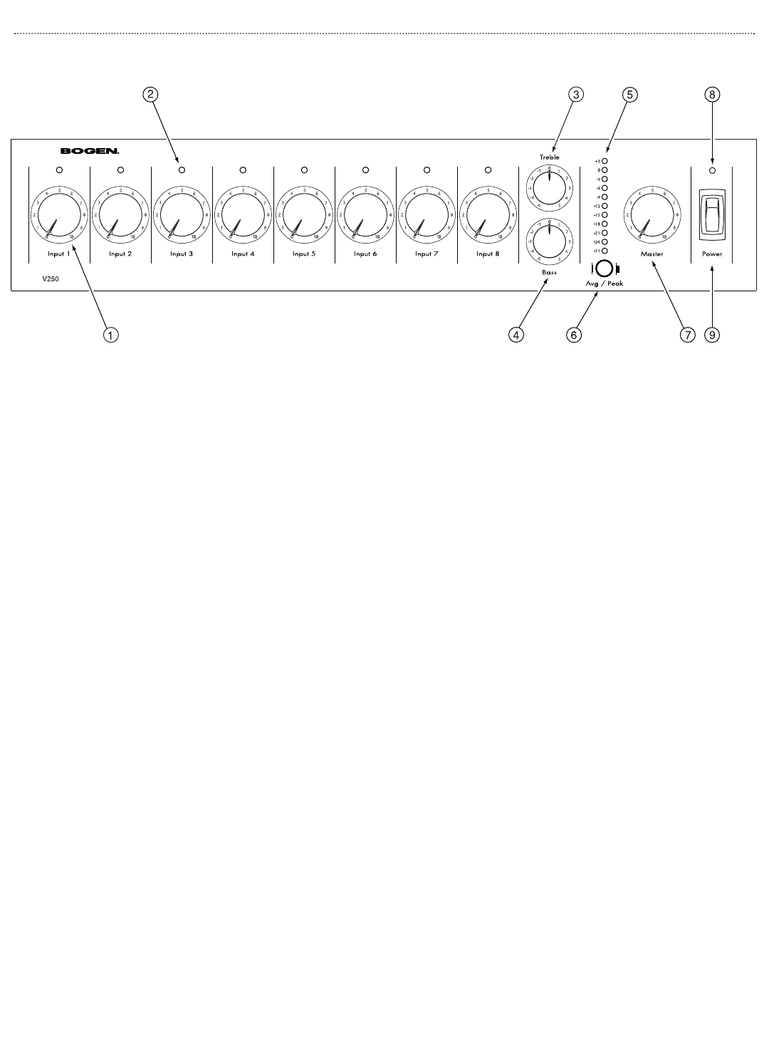
Power Vector Front Panel
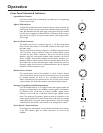
1. Input Volume Control
Each of the 8 inputs is controlled by an independent volume control.
2. Signal / Clip Indicator
A single two-color LED located above each channel’s volume control indicates the audio activity of that
channel’s input. Green indicates signal present at the input; red indicates clipping of the input signal.
3.Treble Control
Controls the amount of cut or boost of treble frequencies above 10 kHz.
4. Bass Control
Controls the amount of cut or boost of bass frequencies below 100 Hz.
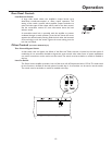
5. LED Output Meter
An 11-segment LED output level meter monitors the output level of the power amplifier.
6.Average / Peak Switch
This switch determines whether the LED Output Meter registers the average or peak level of the amplifier’s
output.
7. Master Volume Control
Controls overall level of mixed input signals.
8. Power Indicator
An LED indicates AC power status.
9. Power Switch
Controls AC power to the amplifier.
2