1. Unplug the unit from electrical source.
2. Remove eight (8) screws securing the unit cover to the
chassis.
3. Slide cover back to remove it from chassis.
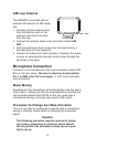
4. Locate Jumper J1 on the circuit board (right side of the unit
as you look at it from front panel).
5. Reposition jumper from CLOSED position to OPEN position.
6. Reinstall cover and screws.
Microphone ALC (Automatic Level Control)
An ALC switch on the rear panel controls the ALC circuit. When
“ON,” the ALC will maintain a consistent level between vari-
ous microphone users
AUX Input
Connect an Aux source to the RCA jacked marked AUX.
PREPAGE OUT
The prepage output lets you route tuner and auxiliary input to a
telephone music-on-hold input. The output is also independent
of the tone and volume controls.
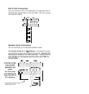
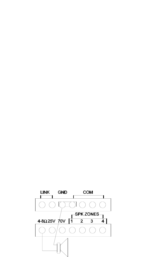
Speaker Connections
4-8
ΩΩ
Direct Connection
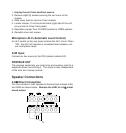
You can connect a 4-8Ω speaker to the terminals marked 4-8Ω
and GND as shown below. Remove the LINK for 4-8
ΩΩ
unbal-
anced output.
5


