


Installation Note
Keep input leads away from the output leads and
AC power cables. Unless the driving source pro-
vides a low-impedance output, keep the input lead
under ten feet in length. Make all connections to
the unit with the POWER switch in the OFF posi-
tion.
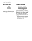
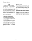
MIC 1- 4
MIC 1 through 4 utilize female XLR-type microphone
connectors. A slide switch located above each XLR
connector is used to supply phantom power for con-
denser microphones.
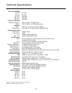
MIC 5/TEL
The MIC 5/TEL input is designed to accept input from
a microphone or from a telephone line. A slide switch
is provided to select MIC 5 or TEL input. To connect a
microphone, place the MIC 5/TEL switch in the MIC
position. Use two conductor shielded cable and con-
nect the cable shield to the center GND terminal. To
use the TEL input, place the MIC 5/TEL switch in the
TEL position and connect the 600 ohm telephone pag-
ing source (dry signal only - no DC voltage) to the MIC
5/TEL screw terminals.
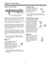
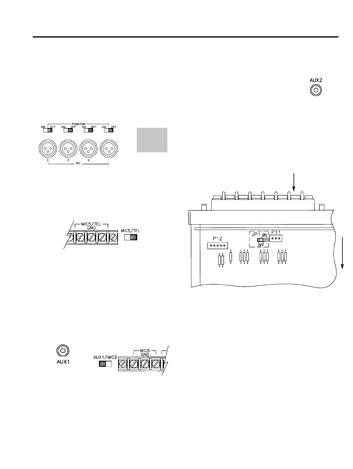
MIC 6/AUX 1
The MIC 6/AUX 1 input is designed to accept input
from a microphone using terminal strip connections or
from a high level auxiliary source such as a tuner or
CD player using the AUX 1 RCA jack. A slide switch is
used to select input type. Connect a microphone to the
screw terminals labeled MIC 6 (works only when AUX
1/MIC 6 switch is in the MIC 6 position). Use two con-
ductor shielded cable and connect the cable shield to
the center GND terminal. Connect an auxiliary input
source to the AUX 1 RCA jack (only works when the
AUX 1/MIC 6 switch is in the AUX1 position).
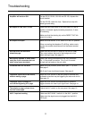
AUX 2
The AUX 2 input uses an RCA plug
and accepts input from a dedicated
AUX source.
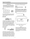
Phantom Power for MIC 5 & MIC 6
A single internal jumper is provided to supply phantom
power to both MIC 5 and MIC 6. The amplifier is
shipped with the jumper in the OFF position. See the
figure below for the location of the phantom power
jumper.
Warning
Removal of the amplifier cover exposes internal
components and presents an electrical shock haz-
ard. For this reason, do not perform any functions
requiring removal of the cover of the amplifier
unless you are qualified to do so. Always discon-
nect AC power from the unit before attempting to
remove the cover.
Input Connections
Phantom Power Jumper Location For
Mic 5 and Mic 6
6
1
2
3
1
2
3
1
2
3
1
2
3
1 — GND
2 — +
3 — -
Front
MIC 5 and MIC 6 input terminal strip