


EMA 255
48
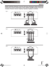
Application options and loudspeaker connection
Stereo mode
Max power 2 x 110 W / 4 Ω Fig. 4, 5
Mono mode
Max power 1 x 330 W / 4 Ω Fig. 6
Stereo mode
Max power 2 x 160 W / 2 Ω Fig. 4, 5
Stereo mode
RMS power 2 x 55 W / 4 Ω Fig. 4, 5
Mono mode
RMS power 1 x 165 W / 4 Ω Fig. 6
Stereo mode
RMS power 2 x 80 W / 2 Ω Fig. 4, 5
Frequency response 10 Hz - 30,000 Hz
Signal-to-noise ratio > 85 dB @ RMS power
Signal-to-noise ratio > 75 dB @ 1 W / 1 kHz
Distortion factor (RMS) < 0.08 %
Stability 2 Ω (4 Ω in bridge mode)
Input sensitivity 0.2 - 10 V
Low-pass lter
(Low Pass) 50 - 250 Hz
High-pass lter
(High Pass) 80 Hz
Bass boost 0 dB / 6 dB / 12 dB
Dimensions
W x H x D (mm)
W x H x D (")
184 x 52.5 x 183
7.25 x 2.1 x 7.2
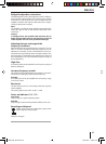
Audio inputs (see Fig. 3)
You can select between 2 di erent audio inputs;
Cinch (RCA)
Hi level (loudspeaker connections)
Use only one of the audio inputs; otherwise, it may lead to
audio interferences.
The preampli er outputs are connected to the cinch (RCA)
sockets
1 via a shielded sound cable.
With control via the loudspeaker outputs, the input connec-
tions of pos.
2/3 are fed to the closest loudspeaker cables
(front or rear) on the left and right. They are separated and
connected to the input connections. The polarity of the
+ or - connections must be observed. Bridge output stages
(BTL) can also be connected directly without an additional
adapter.
–
–
Plus / minus connection
We recommend a minimum cross section of 6 mm
2
.
Route commercially available plus cables to the battery
and connect via fuse holder.
Use cable glands for holes with sharp edges.
Securely fasten commercially available minus cables to a
noise-free earth point (chassis screw, chassis metal) (not
to the minus pole of the battery).
Scrap the contact surfaces of the earth point until they
are bright and grease with graphite grease.
Integrated fuses (Fuse)
The fuses integrated in the ampli er (Fuse) protect the power
ampli er and the entire electrical system in case of an error.
If a replacement fuse is used, never bridge fuses or replace
them with a type with higher current.
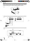
Connection examples
Connection of the voltage supply ...............................Fig. 2
Audio inputs .......................................................................Fig. 3
Loudspeaker connections .............................................Fig. 4/5/6
+12V
Remote connection of the ampli er with switchable +12 V
voltage source.
This allows the ampli er to be switched on and o using the
on/o -switch of the radio device.
Level control
The Level control is used to adjust the input sensitivity of
the power ampli er to the output voltage of your car sound
system preampli er output.
The adjustment range is from 0.2 V to 10 V.
If a car sound system of a third party manufacturer is con-
nected, the input sensitivity must be adjusted corresponding
to the manufacturer data.
A few important explanations in this context:
By turning the control clockwise, the input sensitivity of the
ampli er and, therefore, also the volume increases. However,
this is not a volume control; no further ampli er output
can be achieved in the end position, even if it may sound
like that at the beginning. The system merely increases the
volume faster if the volume control of the car sound system
is turned up.
Loudspeaker connections
(If the ampli er is to be jumpered, continue with the section
"Bridged loudspeaker connections" at this point).
As with every audio component, the correct polarisation of
ampli er and loudspeakers is of essentially importance for a
good bass response. For this reason, ensure that the positive
(+) connection of the ampli er is connected with the posi-
tive connection (+) of the loudspeaker; the same applies to
the negative (-) connections. In addition, the left ampli er
channel must be connected with the left loudspeaker and
the right ampli er channel with the right loudspeaker.
–
–
–
–
–
EMA_255_22LG.indd 48EMA_255_22LG.indd 48 29.07.2011 9:16:01 Uhr29.07.2011 9:16:01 Uhr