


Page 10
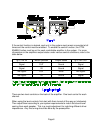
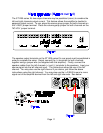
Along with being the right channel input, it is used as the input to the right
bus and the right source for the ‘L+R BUS’. Because it is a BUS input, any
signal input here will appear at the ‘R BUS’ jumper terminal for both of the
ST1200 series II’s jumper modules.
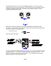
Installing a jumper plug at this terminal on either of the two internal jumper
modules selects the combined signal being carried by both the left and right
inputs. If the left bus and right bus are being used to carry stereo right and
left channels, a jumper plug installed at the ‘L+R BUS’ location will provide
a true L+R mono output.
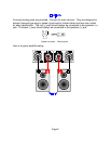
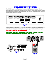
Along with being the left channel input, it is used as the input to the left bus
and the left source for the ‘L+R BUS’. Because it is a BUS input, any signal
input here will appear at the ‘L BUS’ jumper terminal for both of the ST1200
series II’s jumper modules.
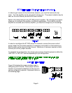
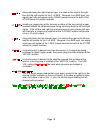
If volume control is desired only from the source, or if outputs are being
combined to obtain higher power, the jumper plug should be installed at the
‘NO VOL’ location.
If volume control is desired at the amplifier, beyond that provided at the
source, a shorting plug is installed at the ‘USE VOL’ location. The ‘USE
VOL’ setting be used when channels are bridged or
combined.
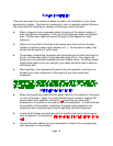
This is a single jumper module that is set apart, up and to the right from the
channel jumper modules on the circuit board. It provides a special function,
when the jumper is set on the ‘-L’ pins, the left bus signal feeding the left
channel will be inverted.