


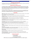
BACK PANEL
F
U
S
E
F
U
S
E
F
U
S
E
F
U
S
E
F
U
S
E
F
U
S
E
F
U
S
E
F
U
S
E
F
U
S
E
F
U
S
E
F
U
S
E
F
U
S
E
F
U
S
E
F
U
S
E
F
U
S
E
F
U
S
E
F
U
S
E
F
U
S
E
F
U
S
E
F
U
S
E
F
U
S
E
F
U
S
E
F
U
S
E
F
U
S
E
F
U
S
E
F
U
S
E
F
U
S
E
F
U
S
E
F
U
S
E
F
U
S
E
FUSE
CAUTION: FOR CONTINUED
PROTECTION AGAINST RISK
OF FIRE REPLACE ONLY WITH
SAME TYPE AND RATING.
CONTROL I/O
CONTROL IN ALLOWS AMPLIFIER
OPERATION WHEN A 5-24V SIGNAL
IS APPLIED WITH A 3.5mm MINI JACK
BK
&
SB
IMPLY ETTER!
CTRL
OUT
12VDC
200mA
CTRL
IN
CHANNEL 1 INPUT CHANNEL 2 INPUT CHANNEL 3 INPUT CHANNEL 4 INPUT CHANNEL 5 INPUT CHANNEL 6 INPUT CHANNEL 7 INPUT
RCA (UNBALANCED)
XLR (BALANCED)
RCA
(UNBALANCED)
XLR
(BALANCED)
+12VLOWPOWER
RING
TIP
GROUND
SLEEVE
+12VCTRLENABLE
www.bkcomp.com
SERIAL #
CHANNEL 6 OUTPUT CHANNEL 7 OUTPUTCHANNEL 5 OUTPUTCHANNEL 4 OUTPUTCHANNEL 3 OUTPUTCHANNEL 2 OUTPUTCHANNEL 1 OUTPUT
POSITIVE
NEGATIVE
POSITIVE
NEGATIVE
POSITIVE
NEGATIVE
POSITIVE
NEGATIVE
POSITIVE
NEGATIVE
POSITIVE
NEGATIVE
POSITIVE
NEGATIVE
AC LINE
High Performance
Audio/Video Systems
Hand-Made in the U.S.A.
RCA (UNBALANCED)
XLR (BALANCED)
RCA (UNBALANCED)
XLR (BALANCED)
CAUTION
RISK OF ELECTRICSHOCK
DO NOT OPEN
RISK OF ELECTRICSHOCK
DO
NOT OPEN
F
U
S
E
F
U
S
E
F
U
S
E
F
U
S
E
F
U
S
E
F
U
S
E
F
U
S
E
F
U
S
E
F
U
S
E
F
U
S
E
F
U
S
E
F
U
S
E
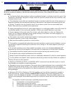
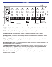
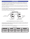
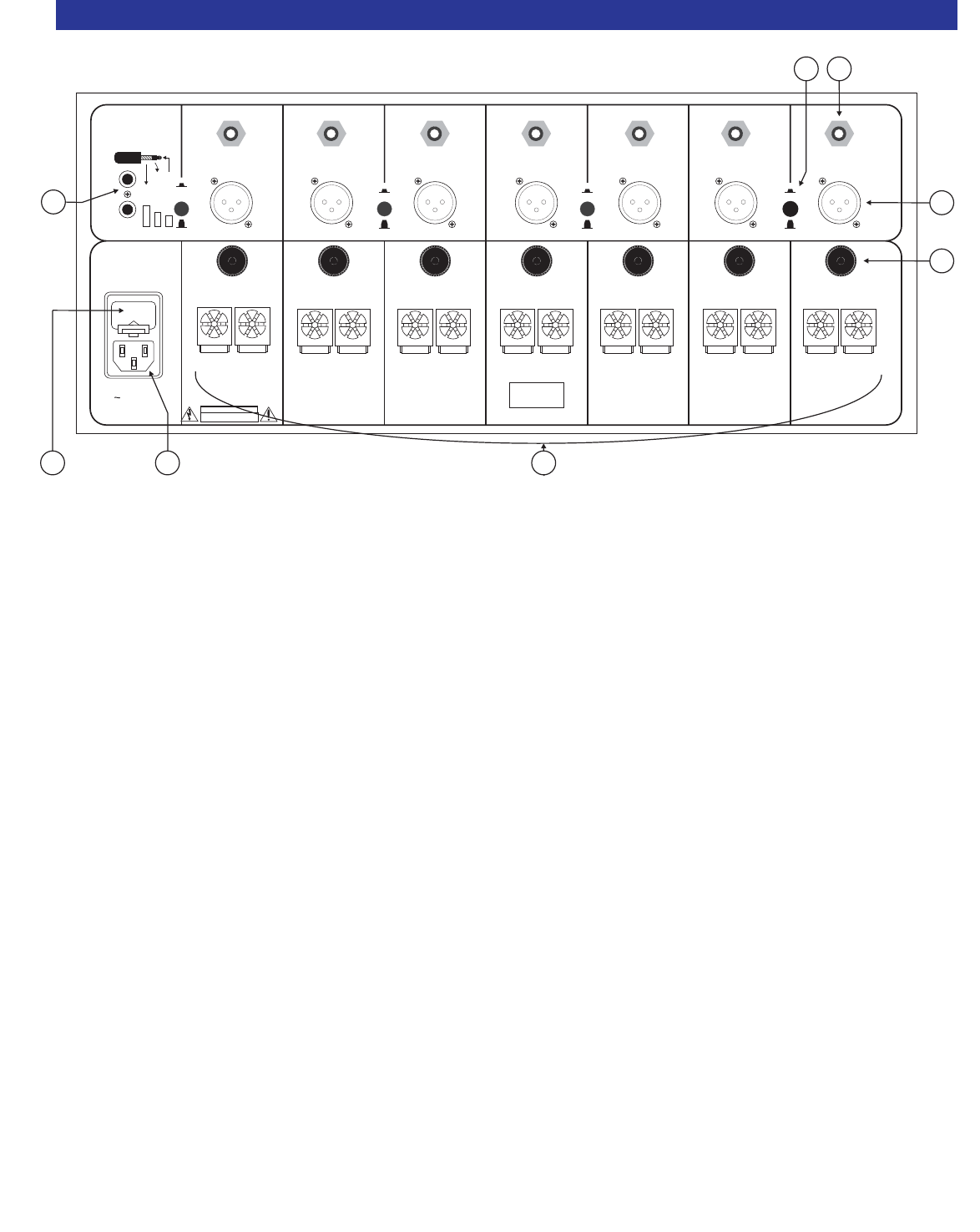
1 2
3
4
5
6
7
8
1. AC Fuse Holder - Holds the AC line fuse. This fuse is a 15 amp / 250 volt slow blow fuse. Replace only
with the same type and value fuse.
2. AC Input Receptacle - For attaching the supplied AC power cord to the amplifier.
3. Speaker Outputs - For connecting the speakers to the amplifier. Explained further on page 6.
4. Speaker Fuses - For protection against amplifier damage in the case of shorted speaker wires. Replace
fuse with the same type and value 6 amp slow blow.
5. Balanced (XLR) Input - For connecting signal patch cables (interconnects) from the preamplifier to the
amplifier. Explained further on page 5 and 6.
6. Unbalanced (RCA) Input - For connecting signal patch cables (interconnects) from the preamplifier to the
amplifier. Explained further on page 5 and 6.
7. Balanced/Unbalanced Input Select - This switch is used to configure an AMPLIFIER PAIR for use as
either balanced (XLR) or unbalanced (RCA) line inputs. This switch controls two amplifier channels and
allows signal patch cables (interconnects) to be sourced from either balanced or unbalanced,
preamplifier/processor or outputs. Explained further on page 5 and 6.
8. Amplifier Control Input/Output - Provides remote switching of the amplifier's standby on/off feature.
Explained further on page 8.
4