


11
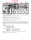
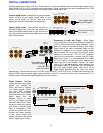
11. Component Video outputs - Switched output connections for your component video monitor.
Red RCA jack - typically connect to the red input on a component video monitor
Green RCA jack - typically connect to the green input on a component video monitor
Blue RCA jack - typically connect to the blue input on a component video monitor
12. Component Video inputs - Switched input connections for three component video devices.
Red RCA jack - typically connect to the red output of a component video source
Green RCA jack - typically connect to the green output of a component video source
Blue RCA jack - typically connect to the blue output of a component video source
13. Line inputs - Connections from your audio/video sources.
Red RCA jacks - right analog audio
White RCA jacks - left analog audio
Yellow RCA jacks - composite video
4 pin din jacks - S-video
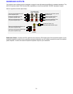
14. Line level outputs - Fixed level outputs to an audio or video recorder.
15. Zone 2 outputs - Variable level outputs to your video monitors and external amplifiers.
16. Zone 1 outputs - Variable level outputs to your video monitors.
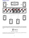
17. Optical Digital inputs - Optical digital inputs are used to connect digital audio signals from your source to the
receiver. The incoming signal may be PCM, Dolby Digital or DTS.
18. Optical Digital output - Zone 1 optical output to carry digital information from the selected digital input of the
receiver out to digital recorders, personal computers, etc.
19. Coax Digital inputs - Coax digital inputs are used to connect digital audio signals from your source to the
receiver. The incoming signal may be PCM, Dolby Digital (AC-3) or DTS.
20. Coax Digital output - Independent Zone 1, and Zone 2, coax outputs to carry digital information from the
selected digital input of the receiver out to digital recorders, personal computers, etc.
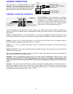
21. AC Line Voltage - Indicates proper voltage and frequency needed to operate your system.
The serial number of your unit is located on the back of the unit.