


5
ULTRA-DI PRO DI800
2. CONTROL ELEMENTS
1.1 Before you get started
1.1.1 Shipment
Your ULTRA-DI PRO was carefully packed at the assembly
plant to assure secure transport. Should the condition of the
cardboard box suggest that damage may have taken place,
please inspect the unit immediately and look for physical
indications of damage.
+ Damaged units should NEVER be sent directly to us.
Please inform the dealer from whom you acquired
the unit immediately as well as the transportation
company from which you took delivery of the unit.
Otherwise, all claims for replacement/repair may
be rendered invalid.
1.1.2 Initial operation
Please make sure the unit is provided with sufficient ventilation,
and never place the ULTRA-DI PRO on top of an amplifier or in
the vicinity of a heater to avoid the risk of overheating.
+ Before plugging the unit into a power socket, please
make sure you have selected the correct voltage:
The fuse compartment near the power plug socket contains
three triangular markings. Two of these triangles are opposite
one another. The voltage indicated adjacent to these markings is
the voltage to which your unit has been set up, and can be
altered by rotating the fuse compartment by 180°. ATTENTION:
This does not apply to export models that were for
example manufactured only for use with 120 V!
+ If you alter the units voltage, you must change the
fuse accordingly. The correct value of the fuse
needed can be found in the chapter
SPECIFICATIONS.
+ Faulty fuses must be replaced with fuses of
appropriate rating without exception! The correct
value of the fuses needed can be found in the
chapter SPECIFICATIONS.
Power is delivered via the cable enclosed with the unit. All
requiered safety precautions have been adhered to.
+ Please make sure that the unit is grounded at all
times. For your own protection, you should never
tamper with the grounding of the cable or the unit
itself.
1.1.3 Warranty
Please take a few minutes and send us the completely filled
out warranty card within 14 days of the date of purchase. You
may also register online at www.behringer.com. The serial number
needed for the registration is located at the top of the unit. Failure
to register your product may void future warranty claims.
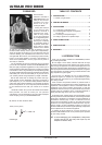
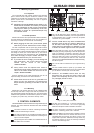
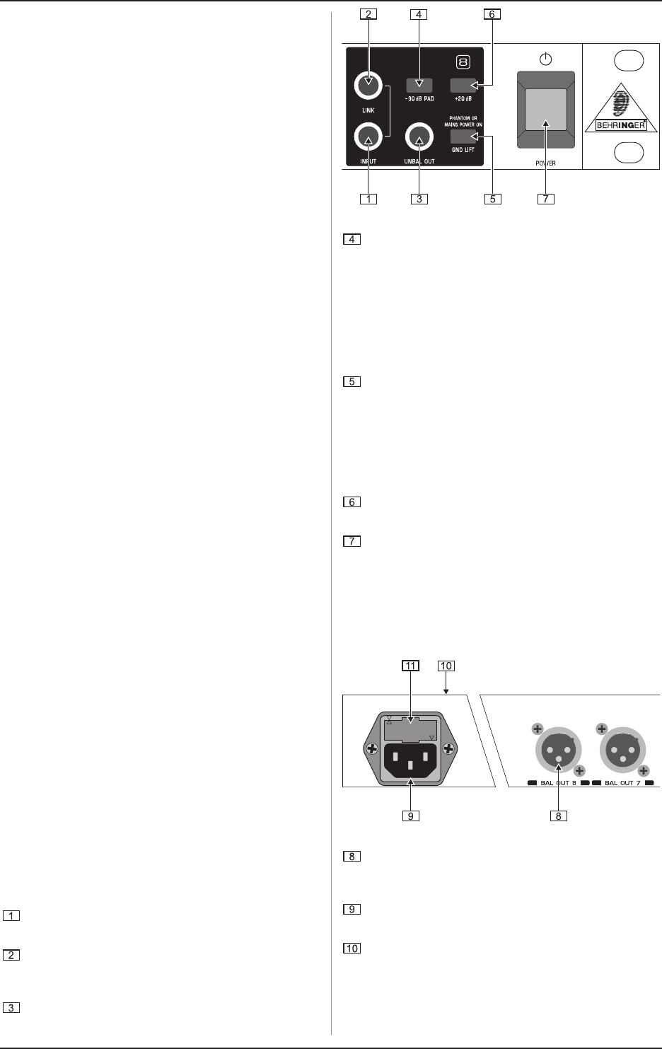
2. CONTROL ELEMENTS
The BEHRINGERULTRA-DI PRO features eight identically built
channels. The control elements described here refer therefore
to all channels.
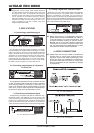
The INPUT connector is used for connecting unbalanced
as well as balanced signal sources.
The LINK connector is the unbalanced parallel output of
the ULTRA-DI PRO, used for example for connecting to an
input of a monitor amplifier.
The input signal is also available in its unbalanced form at
the UNBAL OUT connector.
Fig. 2.1: Front panel control elements
The -30 dB attenuation switch increases the operating
range of the DI800 considerably, from low signal levels of
a high-impedance mic or a guitar, all the way to speaker
connectors of a guitar amplifier.
+ Use the -30 dB switch only when the DI800 starts
distorting (and not the mic preamp). When this is
not the case, avoid using this function, since the
lowest amount of attenuation is desirable in order
to obtain the lowest signal-to-noise ratio possible.
Using the GND LIFT switch, you can fully separate input
and output grounding. Depending on how the equipment to
which your DI800 is connected is grounded, using the
GND LIFT switch lets you lower hum noise or ground loops.
When the GND LIFT switch is depressed, the ground
connection is interrupted (the LED is lit red). When the
switch is in the PHANTOM OR MAINS POWER ON setting,
the LED is lit green.
The +20 dB switch increases the input signal level by
20 dB.
Use the POWER switch to power up your DI800. The
POWER switch should always be in the Off position when
you are about to connect your unit to the mains.
+ Attention: The POWER switch does not fully
disconnect the unit from the mains. Unplug the
power cord completely when the unit is not used
for prolonged periods of time.
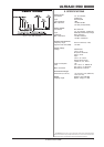
Fig. 2.2: Rear panel connectors
The BAL OUT connectors (1 - 8) are the balanced mic-
level outputs of the channels 1 to 8. Use a high-quality
balanced microphone cable to establish connection.
The mains connection is achieved via the standard IEC
connector. A matching power cord is included.
SERIAL NUBMER. The serial number is located on the top
of the unit. Please take a few minutes and send to us a
completely filled out warranty card within 14 days of the
original date of purchase. Otherwise, warranty claims may
be rendered invalid. Or fill out the warranty information
online at www.behringer.com.