


15
TUBE ULTRAGAIN T1953
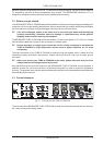
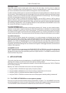
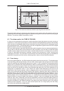
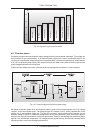
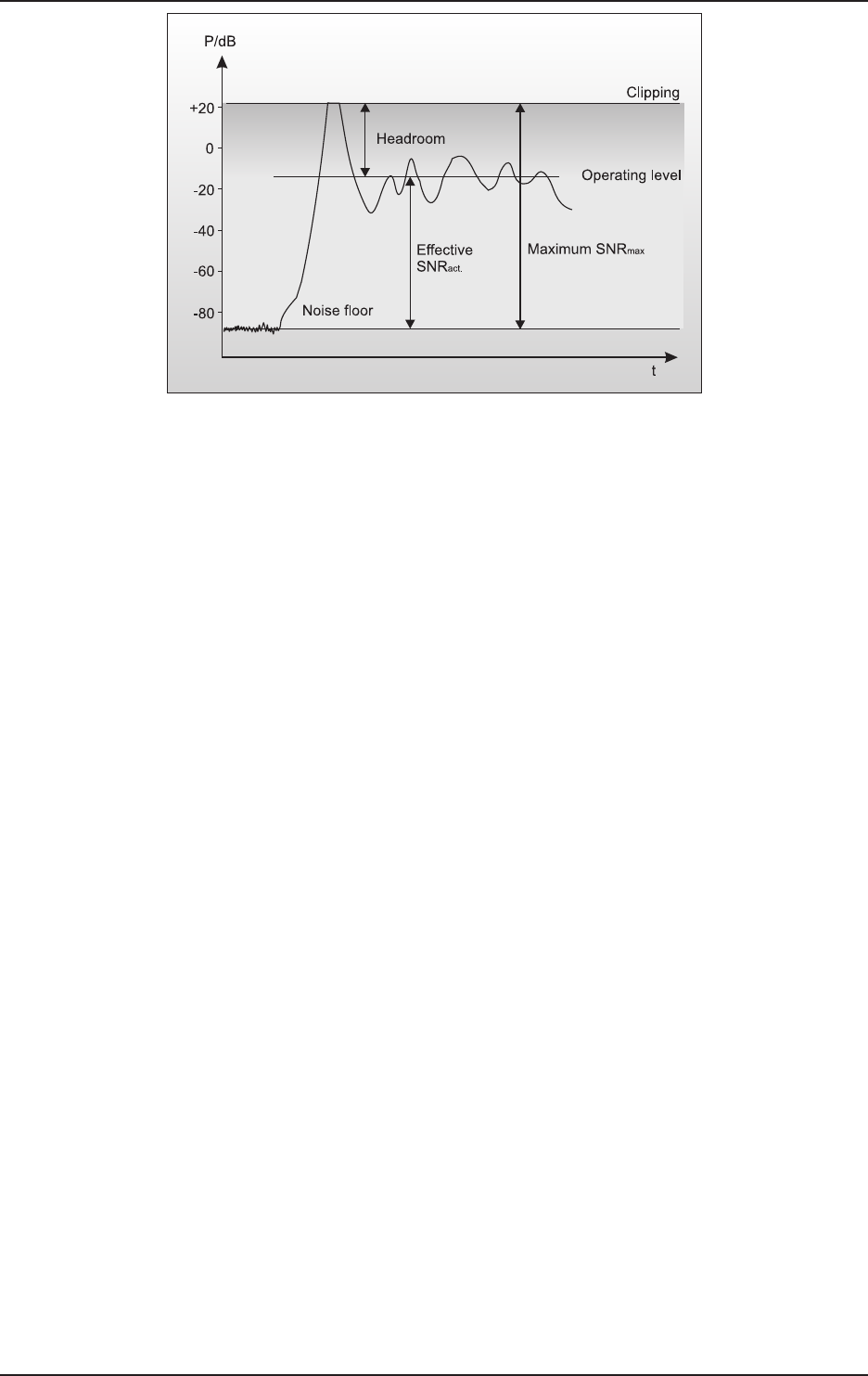
Fig. 4.3: The interactive relationship between operating level and headroom
The need therefore arises for a fast acting automatic gain control system which will constantly monitor the
signals and which will always adjust the gain to maximize the signal-to-noise ratio without incurring signal
distortion. This device is called a compressor or limiter.
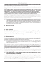
4.2 The tubes used in the TUBEULTRAGAIN
A closer look at developments and trends in audio technology shows that tubes are currently enjoying a
renaissance, in a time when even amateur musicians are free to use digital effects processors and recording
media, and ever more affordable digital mixing consoles are becoming a natural part of the equipment of many
semi-professional studios. The manufacturers try with ever new algorithms to get the most out of DSPs (Digital
Signal Processors), the heart of any digital system.
Still, many audio engineers, particularly old hands often prefer using both old and new tube-equipped devices.
As they want to use their warm sound character for their productions, they are ready to accept that these
goodies produce a higher noise floor than modern, transistor-based devices. As a consequence, you can find
a variety of tube-based microphones, equalizers, preamps and compressors in todays recording and
mastering environments. The combination of semiconductor and tube technologies gives you the additional
possibility of using the best of both worlds, while being able to make up for their specific drawbacks.
4.3 Tube history
Due to many patent litigations, it is difficult to determine exactly when the tube was born. First developments
in tube technology were reported between 1904 and 1906. It was a research task of that time to find a suitable
method for receiving and rectifying high frequencies. On April 12, 1905, a certain Mr. Fleming was granted a
patent for his hot-cathode valve which was based on Edisons incandescent lamp. This valve was used as a
rectifier for high-frequency signals. Robert van Lieben was the first to discover (probably by chance) that the
anode current can be controlled by means of a perforated metal plate (grid), one of the milestones in the
development of amplification tubes. In 1912, Robert van Lieben finally developed the first tube for the
amplification of low-frequency signals. Initially, the biggest problem was to produce sufficient volume levels,
which is why resonance step-ups (though impairing the frequency response) were used to maximize the
attainable volume. Later, the objective was to optimize the electroacoustic transducers of amplifiers in such a
way that a broad frequency band could be transmitted with the least distortion possible. However, a tube-
specific problem is its non-linear amplification curve, i.e. it modifies the sound character of the source material.
Despite all efforts to ensure a largely linear frequency response, it had to be accepted that tube devices
produce a bad sound. Additionally, the noise floor generated by the tubes limited the usable dynamics of
connected storage media (magnetic tape machines). Thus, a one-to-one reproduction of the audio signals
dynamics (expressed as the difference between the highest and lowest loudness levels of the program
material) proved impossible. To top it all, tube devices required the use of high-quality and often costly
transducers and sophisticated voltage supplies.
4. TECHNICAL BACKGROUND